Vardaan Learning Institute
Chapter 9: Household Circuits
Official ICSE Syllabus & Scope
Prescribed Syllabus: Household circuits – main circuit; switches; fuses; earthing; safety precautions; three-pin plugs; colour coding of wires.
Scope of Syllabus: House wiring (ring system), power distribution; main circuit (3 wires – live, neutral, earth) with fuse / MCB, main switch and its advantages – circuit diagram; two-way switch, staircase wiring, need for earthing, fuse, 3-pin plug and socket; conventional location of live, neutral and earth points in 3-pin plugs and sockets. Safety precautions, colour coding of wires.
- Part (A) Transmission of Power & House Wiring: Power transmission grid ($11\text{ kV} \to 132\text{ kV} \to 33\text{ kV} \to 11\text{ kV} \to 220\text{ V}$), 3-wire distribution (Live, Neutral, Earth), company pole fuse, $\text{kWh}$ energy meter, double-pole main switch, Ring system of wiring & advantages, parallel vs series connection of appliances.
- Part (B) Essential Components & Safety: Electric fuse (principle $H = I^2Rt$, solder alloy, $\Delta T \propto I^2/r^3$, live wire rule), MCB, switches (single & double pole, live wire connection rule), dual control switches & staircase wiring circuit, local earthing pit, appliance casing safety earthing, 3-pin plug & socket (rules of earth pin length & thickness), old & new international colour coding of cables, high-tension wires, safety precautions against fire & electric shock.
- Part (C) Solved Numerical Masterclass: Step-by-step solved numericals on appliance power ratings, circuit currents, fuse ratings, and additional load calculations.
PART (A): Transmission of Power and House Wiring System
1. Transmission of Power from Generating Station to Consumer
Electric power is generated at power generating stations (thermal, hydro, or nuclear) which are usually located far away from consumer cities.
Generation Parameters
- Generated Voltage: $11\text{ kV}$ (11,000 Volts).
- Generated Frequency: $50\text{ Hz}$ AC (Alternating Current). Its polarity reverses $100\text{ times per second}$ ($50\text{ cycles/s}$).
- Why Voltage is NOT higher than $11\text{ kV}$ at Generator: Higher voltages cause severe insulation difficulties and dielectric breakdown in the generator windings.
- Why Voltage is NOT lower than $11\text{ kV}$ at Generator: Lower voltages produce excessively large currents, demanding extremely thick copper conductors and causing huge internal heating.
- Why AC is generated (not DC): Alternating current (AC) voltage can be easily and efficiently stepped up or stepped down using transformers with negligible power loss. Direct current (DC) cannot be transformed via stationary transformers.
2. Why Power is Transmitted at High Voltage ($132\text{ kV}$)
Electric power from the generating station is transmitted over long distances at a very high voltage ($132\text{ kV}$) rather than $11\text{ kV}$ to minimize $I^2Rt$ power loss in line wires.
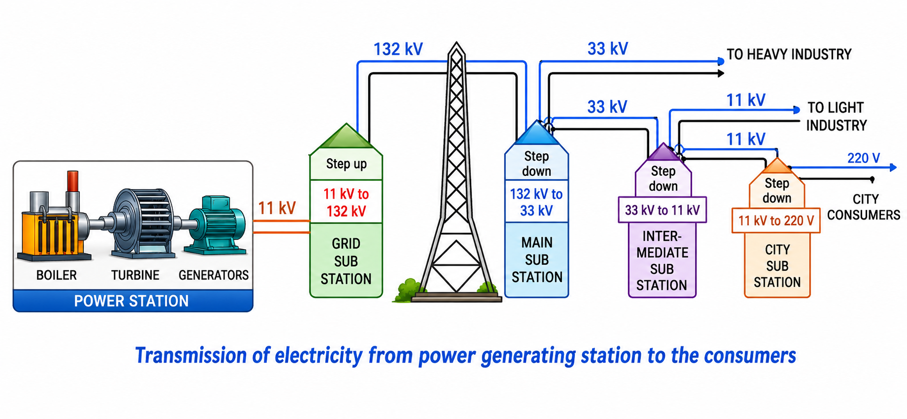
Left: Power generation at 11 kV. Center: Step-up to 132 kV for grid transmission. Right: Step-down stages through substations to 220 V consumer supply.
3. Stages of Voltage Step-Up and Step-Down in Power Grid
| Substation Stage |
Transformer Type |
Voltage Level |
Supplied Consumer / Purpose |
| Power Station |
AC Alternator |
$11\text{ kV}, 50\text{ Hz}$ |
Power generation. |
| Grid Sub-station |
Step-Up Transformer |
$11\text{ kV} \to 132\text{ kV}$ |
Long-distance main grid transmission over high-tension pylons. |
| Main Sub-station |
Step-Down Transformer |
$132\text{ kV} \to 33\text{ kV}$ |
Feeds heavy industries & intermediate substations. |
| Intermediate Sub-station |
Step-Down Transformer |
$33\text{ kV} \to 11\text{ kV}$ |
Feeds light industries & city substations. |
| City Sub-station |
Step-Down Transformer |
$11\text{ kV} \to 220\text{ V}$ |
Supplies single-phase $220\text{ V}, 50\text{ Hz}$ to domestic city consumers. |
4. Power Distribution to a House
To supply electric power from the city sub-station transformer to a house, an overhead cable on poles or an underground cable is used. The cable consists of three wires:
- Live (or Phase) Wire ($L$): Carries current from the source to the distribution board at a potential of $220\text{ V}$.
- Neutral Wire ($N$): Acts as the return path for current back to the source at zero potential ($0\text{ V}$).
- Earth Wire ($E$): Connected to a thick metal plate buried deep in the ground locally at zero potential ($0\text{ V}$).
The neutral wire ($N$) and the earth wire ($E$) are connected together at the local city sub-station so that the neutral wire is strictly maintained at zero potential ($0\text{ V}$).
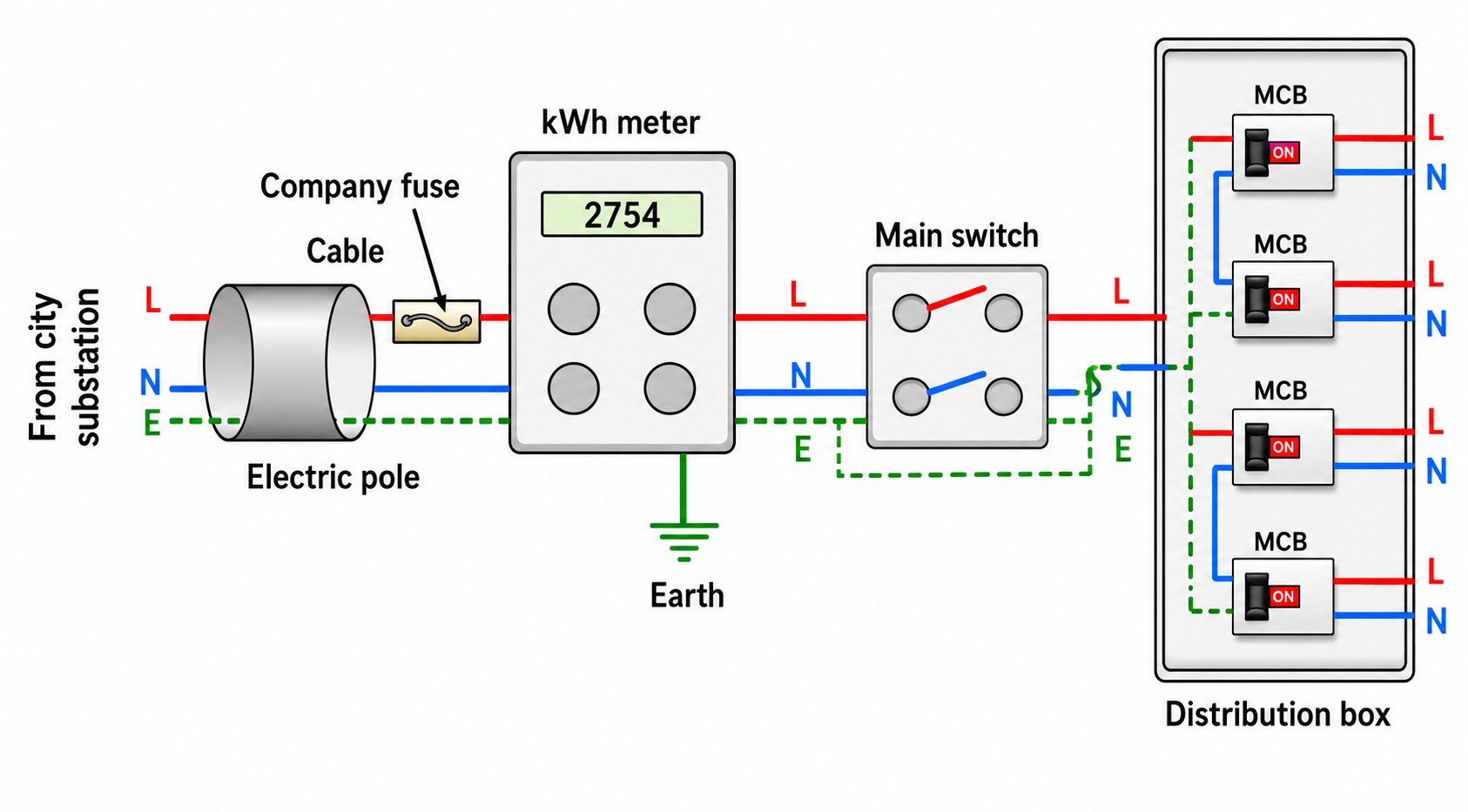
Left: Incoming 3-core cable from pole fuse. Center: kWh meter and double-pole main switch. Right: Distribution board with MCBs.
5. Essential Pathway Before Reaching Domestic Appliances
- Company Fuse (or Pole Fuse):
- Connected in the Live Wire ($L$) at the pole or just before the electric meter.
- Has a high current rating ($\approx 50\text{ A}$).
- Only authorized personnel of the electricity supply company are permitted to handle or replace this fuse.
- Kilowatt-Hour Meter ($\text{kWh}$ Meter):
- Mounted on the front or outer wall of the house to record total electrical energy consumed in $\text{kWh}$ (units).
- Both Live and Neutral wires enter the meter and exit to the consumer main switch.
- Main Switch (Double-Pole Switch):
- Connected after the meter. It is a double-pole switch with an earthed iron/metal casing.
- Crucial Advantage: It breaks the connections of both the Live and Neutral wires simultaneously from the main supply, isolating the entire household during repairs or emergencies.
- Consumer Unit / Distribution Box:
- Contains the Main Fuse (or Master MCB of $\approx 30\text{ A}$) in the live wire.
- Splits supply into separate parallel circuits (e.g. $5\text{ A}$ lighting circuits and $15\text{ A}$ power circuits), each guarded by its own individual fuse or MCB.
6. House Wiring — The Ring System
In modern houses, the Ring System of wiring is universally adopted. In this system, wires starting from the distribution box run around all rooms in a closed continuous ring and then return back to the distribution box.
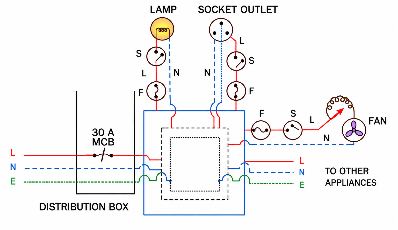
Left: 30 A distribution box. Center & Right: Ring circuit providing dual current paths to lamps, sockets, and ceiling fan.
4 Key Advantages of Ring System
- Dual Current Path & Reduced Wire Thickness: Current from the distribution box can reach an individual appliance through two separate paths around the ring. Thus, the effective wire cross-section is doubled, allowing thinner wire to be used and drastically reducing wiring material cost.
- Individual Fuse Protection: Every appliance has a separate fuse. If a fault causes an appliance fuse to blow, all other appliances continue to operate uninterrupted.
- Uniform Socket Size: Plugs and sockets across rooms can be standardized in physical size, while each socket is protected by a fuse rated specifically for the connected appliance.
- Easy Expansion: Installing a new appliance does not require running new cables all the way from the distribution box; it can be tapped directly from the nearest ring circuit point in the room.
7. Parallel Connection of Household Appliances
All electrical appliances in a household (bulbs, fans, refrigerators, air conditioners) are connected in PARALLEL with the mains supply.
Advantages of Parallel Connection
- Full Rated Voltage ($220\text{ V}$): Each appliance receives the full $220\text{ V}$ supply across its terminals, allowing it to draw its rated current and operate at peak efficiency.
- Independent Operation: Each appliance has its own independent switch in the live wire. Switching off or failure of one appliance has zero effect on the working of other appliances.
Why Series Connection is Never Used in Houses
- Voltage Division: The $220\text{ V}$ supply divides among appliances in proportion to their resistances ($V = V_1 + V_2 + \dots$), leaving each appliance with insufficient voltage to operate.
- Reduced Current & Power: Adding more appliances in series increases total circuit resistance ($R_s = R_1 + R_2 + \dots$), significantly diminishing total current and power delivered to each unit.
- Dependent Operation: If one appliance burns out or is switched off, the entire circuit is broken, and all other appliances immediately stop working.
PART (B): Essential Safety Components of House Wiring
1. Electric Fuse
Electric Fuse: A safety device containing a short, thin wire of low melting point and high resistance that limits the maximum current flowing in a circuit by melting and breaking the circuit when current exceeds its rated limit.
Fuse Wire Material Characteristics
- Alloy Composition: Made of an alloy of Lead ($50\%$) and Tin ($50\%$) (Solder alloy).
- Low Melting Point: Melting point is low ($\approx 250^\circ\text{C}$), so it melts quickly upon excessive heating.
- High Specific Resistance ($\rho$): Its resistivity is significantly higher than that of copper or aluminium, generating sufficient Joule heat with minimal current excess.
- Why Copper/Aluminium wire CANNOT be used as Fuse:
- Copper and aluminium have very high melting points ($\approx 1080^\circ\text{C}$ and $660^\circ\text{C}$). They will not melt during overloads and can ignite household fires!
- Their low resistivity means an ordinary copper wire will allow dangerous overcurrents to pass without blowing.
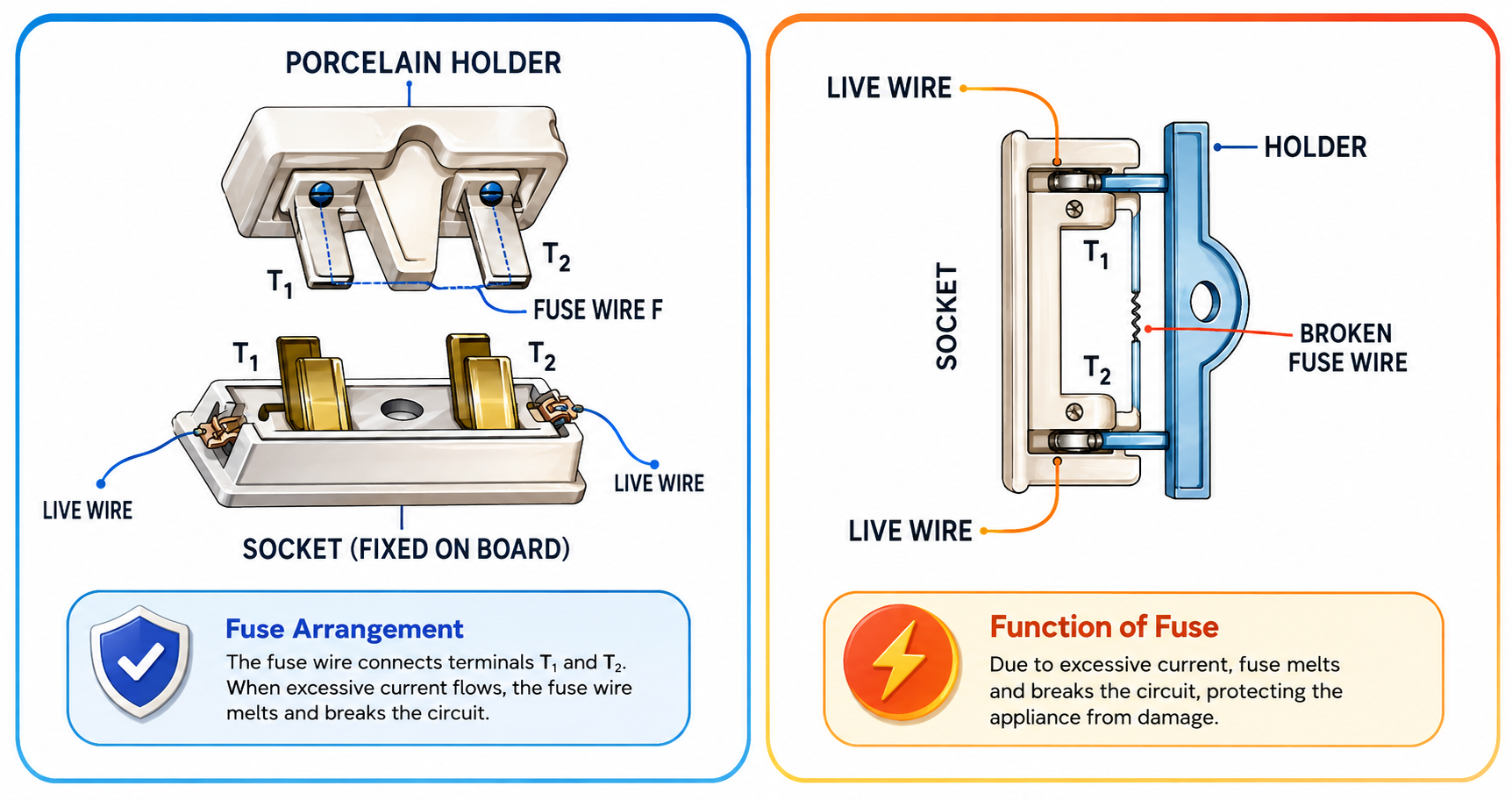
Left: Rewirable porcelain fuse holder and socket. Right: Melting of fuse wire breaks the circuit safely during overload.
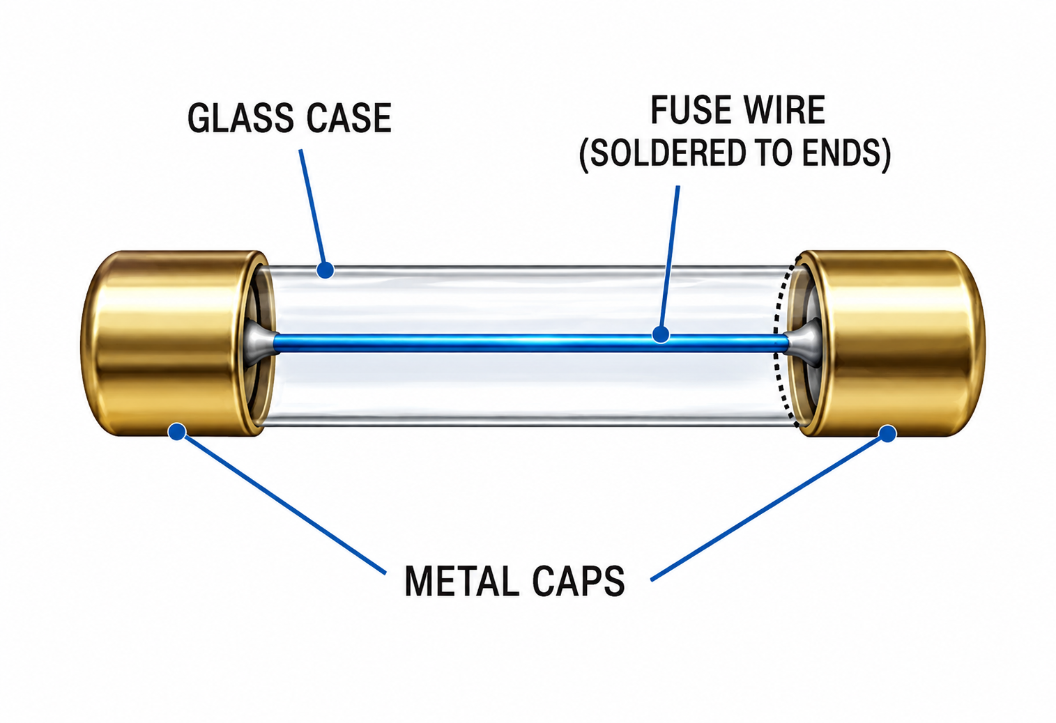
Cylindrical glass cartridge fuse with metal contact caps used in modern electronic appliances.
2. Why the Fuse MUST ALWAYS Be Connected in the LIVE Wire
The fuse is strictly connected in the Live Wire ($L$) before the appliance. Connecting it in the neutral wire is extremely dangerous and hazardous.
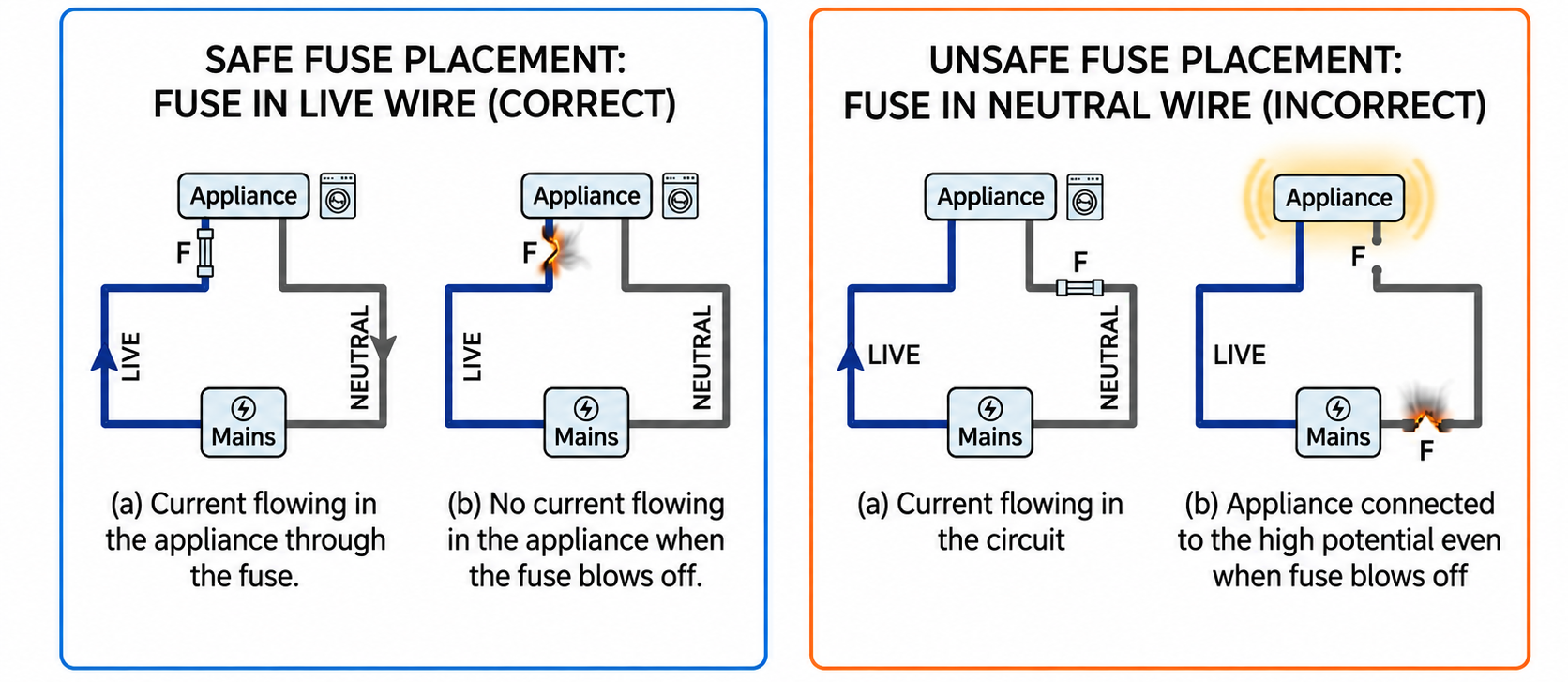
Left: Fuse in live wire isolates appliance at safe 0 V. Right: Fuse in neutral wire leaves appliance live at 220 V even after blowing.
| Fuse Position |
When Fuse Blows (Circuit Incomplete) |
Safety Status for Human Touch |
| Connected in LIVE Wire (Correct) |
The live wire is cut off before the current reaches the appliance. The appliance drops to $0\text{ V}$ (ground potential). |
100% SAFE: A person touching the appliance receives no shock. |
| Connected in NEUTRAL Wire (Hazardous) |
The neutral return wire breaks, stopping the current, but the appliance remains connected directly to the $220\text{ V}$ live wire! |
FATAL SHOCK RISK: If a person touches the appliance, current flows through their body into the earth! |
3. Current Rating of a Fuse
The current rating is the maximum safe current a fuse wire can carry continuously without melting.
| Appliance |
Power Rating at $220\text{ V}$ |
Running Current ($I = P/V$) |
Standard Fuse Rating |
| Electric Bulb |
$60\text{ W}$ |
$0.27\text{ A}$ |
$5\text{ A}$ (Line circuit) |
| Television Set |
$120\text{ W}$ |
$0.54\text{ A}$ |
$5\text{ A}$ (Line circuit) |
| Refrigerator |
$150\text{ W}$ |
$0.68\text{ A}$ |
$5\text{ A}$ (Line circuit) |
| Electric Mixer |
$750\text{ W}$ |
$3.4\text{ A}$ |
$5\text{ A}$ (Line circuit) |
| Room Heater / Iron |
$1000\text{ W}$ |
$4.5\text{ A}$ |
$5\text{ A}$ |
| Electric Geyser |
$1500\text{ W}$ |
$7.0\text{ A}$ |
$8\text{ A}$ / $10\text{ A}$ |
| Electric Kettle |
$2000\text{ W}$ |
$8.3\text{ A}$ / $9.1\text{ A}$ |
$10\text{ A}$ |
| Electric Oven / AC |
$3000\text{ W}$ |
$13.6\text{ A}$ |
$15\text{ A}$ |
4. Miniature Circuit Breaker (MCB)
Modern electrical distribution boxes employ Miniature Circuit Breakers (MCBs) instead of traditional fuse wires for each circuit.
- Automatic Trip Mechanism: An MCB uses an electromagnetic mechanism that automatically snaps/trips off in less than $25\text{ milliseconds}$ upon sensing an overload or short circuit.
- Key Advantages over Fuses:
- No need to replace wire; simply raise the lever once the fault is cleared.
- Extremely fast tripping time ($\approx 25\text{ ms}$) provides superior protection against electrical fire and appliance damage.
5. Switches
Switch: An on-off device connected in the Live Wire ($L$) to start or stop current flow through an appliance.
Why Switch MUST be in Live Wire
- In Live Wire: When the switch is 'OFF', the appliance is isolated from the live wire and drops to zero potential ($0\text{ V}$). Touching the internal element or socket during cleaning or repairs is completely safe.
- In Neutral Wire: When the switch is 'OFF', the current stops because the return path is broken, but the appliance remains at $220\text{ V}$ live potential. A person touching the element while standing on the floor completes the path to earth and receives a fatal shock!
6. Circuits with Dual Control Switches (Staircase Wiring)
A Dual Control Switch (Two-Way Switch) is a single-pole double-throw (SPDT) switch containing three terminals ($a, b, c$) with a pivoting springy metal contact strip. It enables a light bulb to be controlled independently from two different locations (such as bottom and top of a staircase, or both ends of a long corridor).
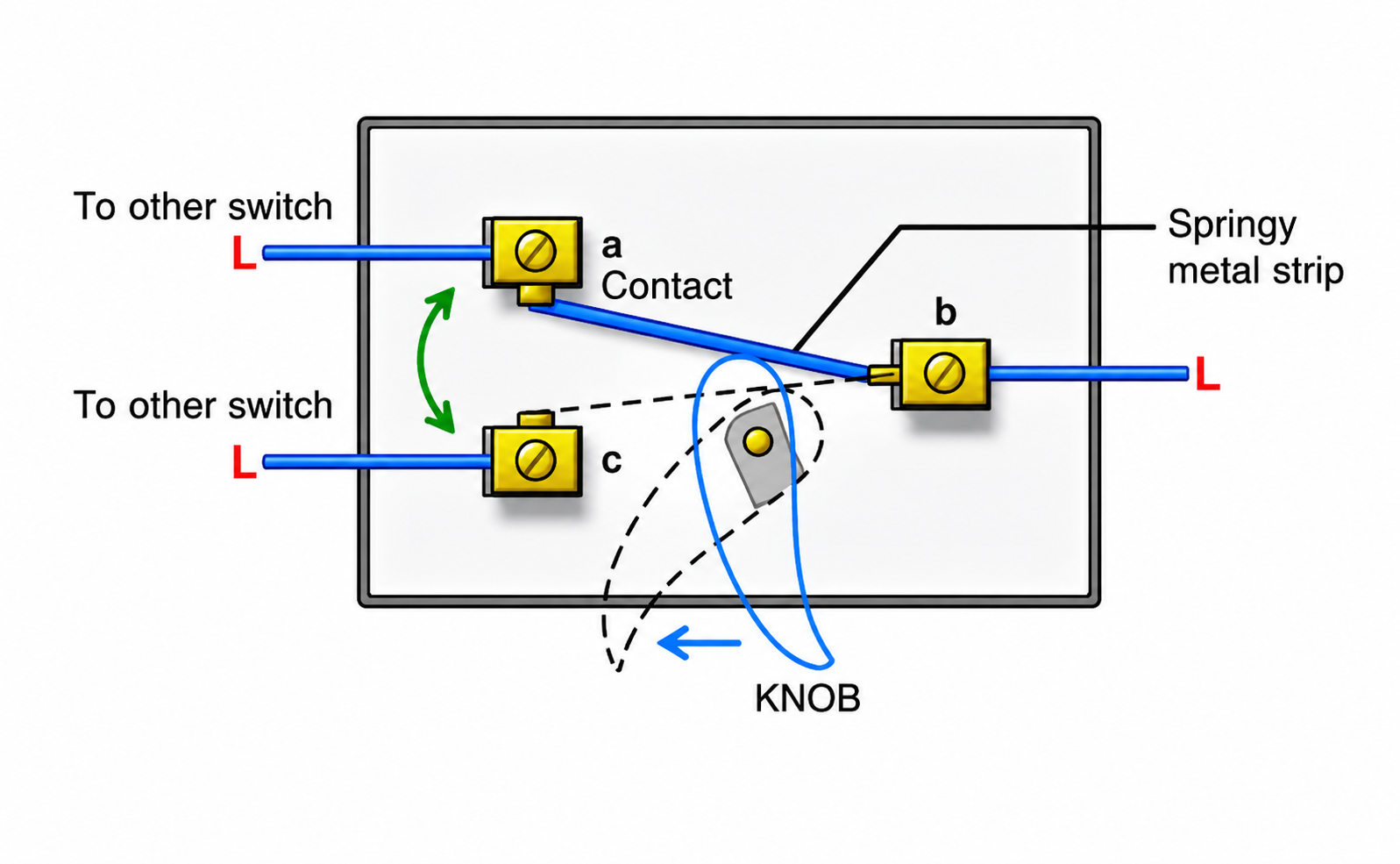
Internal rocking contact strip toggling connection between terminals b-a and b-c.
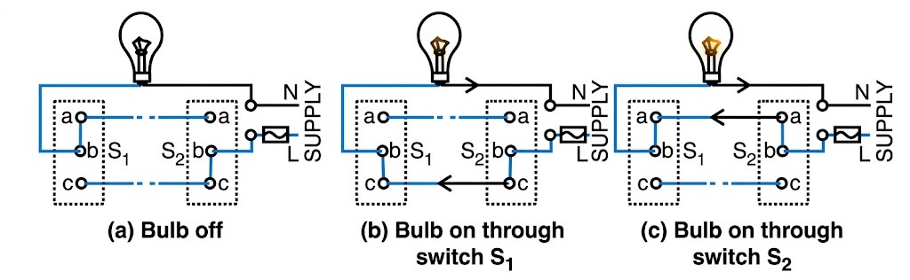
Staircase circuit states: (a) Bulb OFF, (b) Bulb ON via switch S1, (c) Bulb ON via switch S2.
| Switch $S_1$ (Ground Floor) |
Switch $S_2$ (First Floor) |
Circuit Path |
Bulb Condition |
| Position $a$ (contacts $b-a$) |
Position $c$ (contacts $b-c$) |
Open (Incomplete) |
OFF |
| Position $c$ (contacts $b-c$) |
Position $c$ (contacts $b-c$) |
Closed via lower rail ($c-c$) |
ON (Lights Up) |
| Position $a$ (contacts $b-a$) |
Position $a$ (contacts $b-a$) |
Closed via upper rail ($a-a$) |
ON (Lights Up) |
| Position $c$ (contacts $b-c$) |
Position $a$ (contacts $b-a$) |
Open (Incomplete) |
OFF |
7. Earthing (Grounding)
Earthing means connecting the electrical circuit or the metallic body of an appliance to the general mass of the Earth by means of a zero-resistance wire.
(a) Local Earthing (at the Meter)
- A hole $2-3\text{ metres}$ deep is dug near the kWh meter outside the house.
- A thick copper plate ($50\text{ cm} \times 50\text{ cm}$) is welded to a thick copper rod and buried at the bottom.
- The copper plate is packed in a mixture of charcoal and common salt with water poured through a pipe to keep the ground damp and maintain excellent electrical conductivity (very low earth resistance).
- The top end of the copper rod is connected to the Earth terminal of the meter and distribution board.
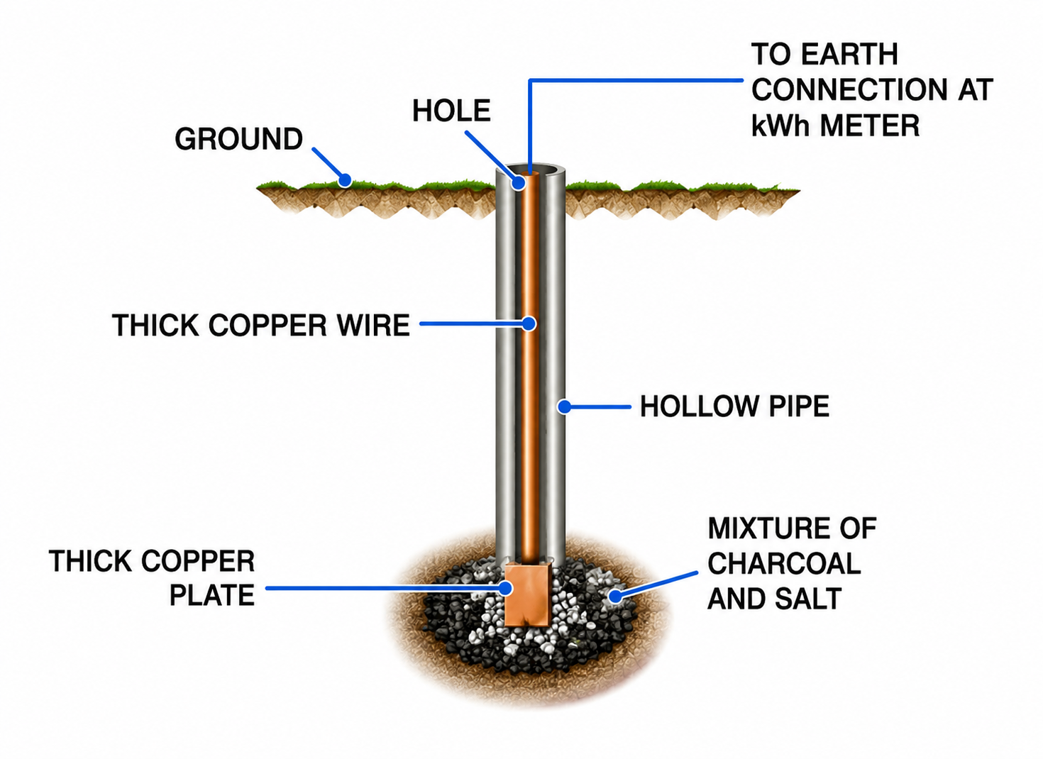
Local earthing pit with buried copper plate embedded in damp charcoal and salt mixture.
(b) Appliance Safety Earthing
The metallic outer body of high-power appliances (refrigerator, electric iron, toaster, geyser) is connected to the green earth wire.
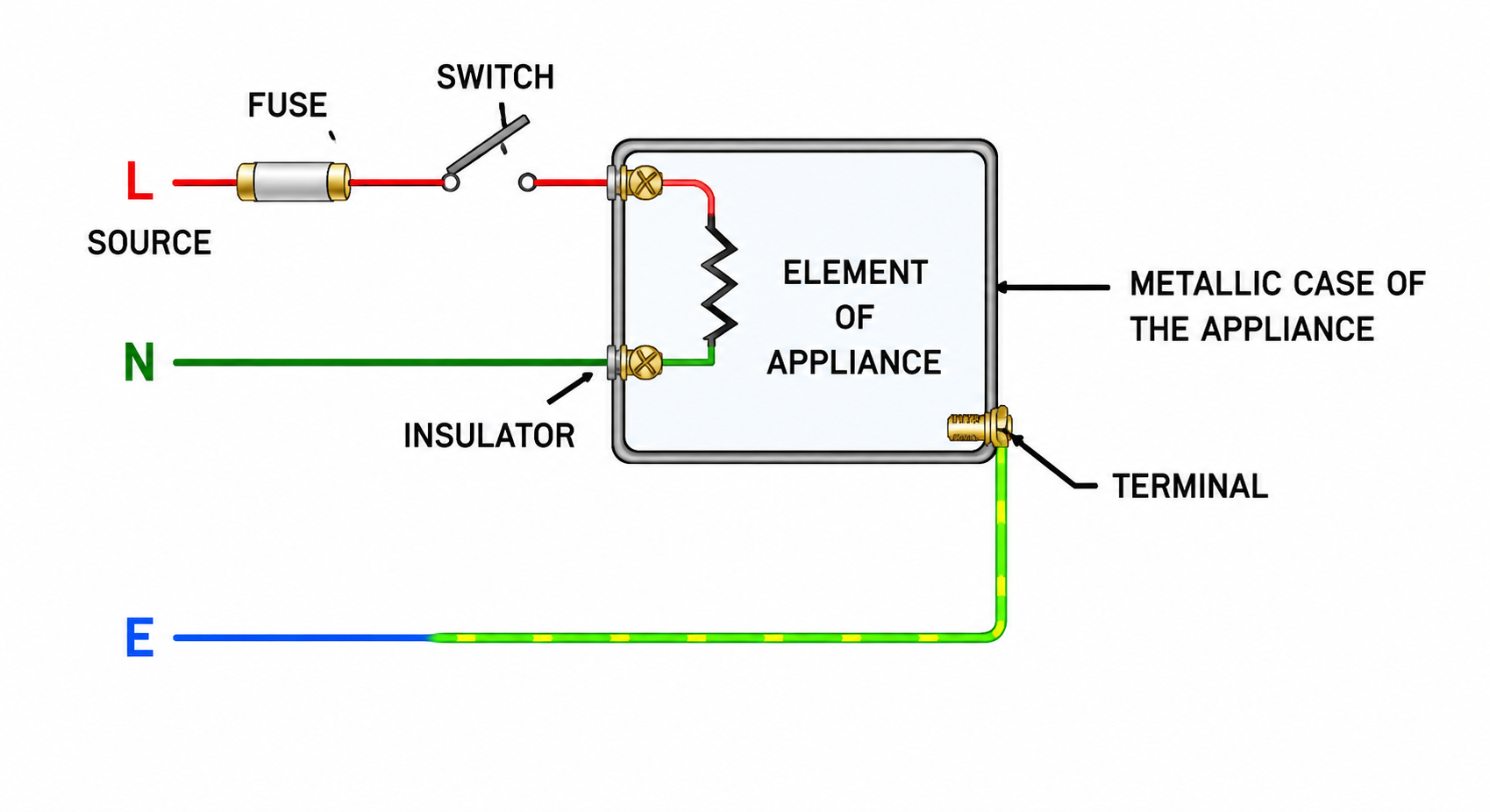
Safety earthing route: Current diverts safely to ground, blowing the live fuse and preventing electric shock.
- If the live wire insulation wears out and touches the metal casing, the entire casing is energized at $220\text{ V}$.
- Since the casing is connected to the zero-resistance earth wire, a massive surge of current flows directly into the earth instead of passing through the human body ($R_{\text{earth}} \approx 0 \ \Omega \ll R_{\text{human}} \approx 1000\ \Omega$).
- This intense current surge immediately melts the live wire fuse (or trips the MCB), completely cutting off the electrical supply and saving the user from electric shock!
8. Three-Pin Plug and Three-Pin Socket
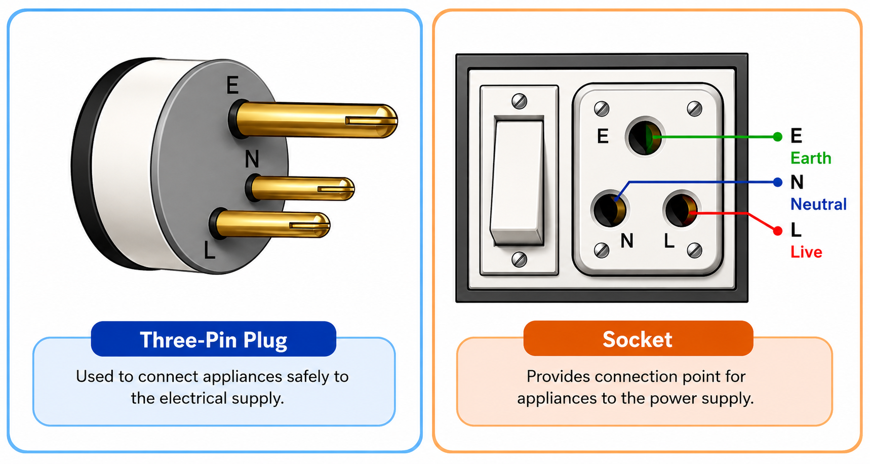
Standard 3-pin plug (Earth top, Live left, Neutral right) and matching 3-hole wall socket.
Two Inviolable Rules of the Earth Pin
- Why the Earth Pin is LONGER than Live and Neutral pins:
Being longer, the earth pin enters the socket first and establishes earth protection BEFORE the live pin connects to high potential. When unplugging, the earth pin disconnects LAST, ensuring safety throughout insertion and withdrawal.
- Why the Earth Pin is THICKER than Live and Neutral pins:
Its larger diameter physically prevents the earth pin from being accidentally inserted into the live or neutral holes of the socket.
- Why Brass Pins are Split at the Ends:
The split provides spring tension, creating a tight, low-resistance frictional fit in the socket hole to prevent loose connections, sparking, and burning.
9. Colour Coding of Wires in a Cable
A standard 3-core flexible cable uses standard colour insulation to prevent wiring mistakes:
| Wire Function |
Old Convention Colour |
New International Convention Colour |
Connected Socket / Plug Location |
| Live Wire ($L$) |
Red |
Brown |
Right pin / hole (facing socket) |
| Neutral Wire ($N$) |
Black |
Light Blue |
Left pin / hole (facing socket) |
| Earth Wire ($E$) |
Green |
Green or Yellow |
Top larger pin / hole |
10. High Tension (HT) Wires
High tension overhead cables carry heavy currents at high voltages.
- Construction: Made by twisting together a large number of thin insulated copper/aluminium strands instead of a single thick solid wire.
- Reason: A bundle of twisted thin strands provides a much larger surface area than a solid wire of equal cross-section, allowing Joule heat to radiate away rapidly into the atmosphere and preventing overheating and sagging.
11. Safety Precautions Against Electrical Hazards
5 Golden Rules of Electrical Safety
- Dry Hands: Never touch switches, sockets, or appliances with wet hands ($R_{\text{wet skin}} \approx 1000\ \Omega$, leading to lethal current flow).
- Proper Insulation: Regularly check cable insulation for cracking or brittleness over time.
- Correct Live Wire Fuse: Never use a fuse with a rating higher than the circuit cable capacity; never bypass with copper wire.
- Mandatory Appliance Earthing: Ensure all metal-bodied heating and motorized appliances are properly grounded.
- Independent Switches in Live Wire: Always place switches in the live wire so that switching 'OFF' isolates the device from the $220\text{ V}$ supply.
PART (C): Solved Numerical Examples Masterclass
Q. An electric motor of power $3\text{ kW}$ is operated at mains supply of $220\text{ V}$. Calculate: (i) current drawn by the motor, (ii) minimum current rating of the fuse to be connected with the motor.
Given: Power $P = 3\text{ kW} = 3000\text{ W}$, Mains Voltage $V = 220\text{ V}$.
(i) Running Current Drawn:
$$ I = \frac{P}{V} = \frac{3000}{220} = \mathbf{13.64\text{ A}} $$
(ii) Fuse Rating: The fuse rating must be slightly greater than the running current. Therefore, the standard fuse rating to be used is $15\text{ A}$.
Q. A house has a main fuse of $5\text{ A}$ rating on a $220\text{ V}$ line. In the house, 5 bulbs each of $60\text{ W}$ and 2 tube-lights each of $40\text{ W}$ are used simultaneously. Calculate: (i) the total current drawn from the mains, (ii) the maximum number of additional $100\text{ W}$ bulbs that can be safely switched on simultaneously during a festival.
(i) Current Drawn by Present Load:
$$ P_{\text{present}} = (5 \times 60) + (2 \times 40) = 300 + 80 = 380\text{ W} $$
$$ I_{\text{present}} = \frac{P}{V} = \frac{380}{220} = \mathbf{1.73\text{ A}} $$
(ii) Additional $100\text{ W}$ Bulbs Capacity:
$$ I_{\text{excess available}} = I_{\text{max}} - I_{\text{present}} = 5\text{ A} - 1.73\text{ A} = \mathbf{3.27\text{ A}} $$
Current drawn by each $100\text{ W}$ bulb: $I_{\text{bulb}} = \frac{100}{220} = 0.455\text{ A}$.
$$ n = \frac{I_{\text{excess}}}{I_{\text{bulb}}} = \frac{3.27}{0.455} = 7.19 $$
Answer: A maximum of 7 additional bulbs of $100\text{ W}$ can be safely switched on without blowing the $5\text{ A}$ main fuse.
Q. An electric bulb is rated $220\text{ V}, 60\text{ W}$.
(i) Calculate the resistance of its filament.
(ii) If two such identical bulbs are connected in series across $220\text{ V}$ mains, find the total power consumed.
(iii) If they are connected in parallel across $220\text{ V}$ mains, find the total power consumed.
(i) Resistance of Filament ($R$):
$$ R = \frac{V^2}{P} = \frac{(220)^2}{60} = \frac{48400}{60} = \mathbf{806.67 \ \Omega} $$
(ii) Two Bulbs in Series across $220\text{ V}$ Mains:
Total series resistance $R_s = R + R = 2R = 2 \times 806.67 = 1613.33 \ \Omega$.
$$ P_{\text{series}} = \frac{V^2}{R_s} = \frac{(220)^2}{2R} = \frac{60}{2} = \mathbf{30\text{ W}} \quad (\text{Each bulb glows at } 15\text{ W}) $$
(iii) Two Bulbs in Parallel across $220\text{ V}$ Mains:
Each bulb receives full $220\text{ V}$ and consumes $60\text{ W}$.
$$ P_{\text{parallel}} = 60\text{ W} + 60\text{ W} = \mathbf{120\text{ W}} $$
Q. An electric kettle is rated $3\text{ kW}, 250\text{ V}$. Can it be safely used in a circuit protected by a $13\text{ A}$ fuse? Give a numerical reason.
Calculation of Safe Operating Current:
$$ I = \frac{P}{V} = \frac{3000\text{ W}}{250\text{ V}} = \mathbf{12\text{ A}} $$
Conclusion: Yes, the kettle can be safely operated in the circuit because the operating current ($12\text{ A}$) is less than the fuse rating ($13\text{ A}$).

 VARDAAN COMET