Created by Team Vardaan with ♥|Powered byVARDAAN COMET
Chapter 8: Current Electricity
Chapter Overview & Scope
This master note document covers the complete syllabus for Class 10 Physics (Chapter 8: Current Electricity), encompassing every single concept, definition, derivation, comparative table, diagram, and numerical problem:
Part (A): Charge ($q$), Current ($I$), Potential ($V$), Potential Difference ($V_A - V_B$), Microscopic Origin of Resistance, Ohm's Law ($V = IR$), Experimental Verification, $V$-$I$ Slope, Ohmic vs Non-Ohmic Resistors, Factors affecting Resistance, Specific Resistance ($\rho$), Choice of Wires, Superconductors.
Part (B): E.M.F. ($\mathcal{E}$), Terminal Voltage ($V$), Voltage Drop ($v = Ir$), Internal Resistance ($r$), Series and Parallel Resistor Derivations, Branching Rules.
Part (C): Electrical Energy ($W$), Electrical Power ($P$), Joule's Law of Heating ($H = 0.24 I^2Rt\text{ cal}$), Commercial Unit ($\text{kWh}$), Appliance Ratings, Household Energy Bill Calculations.
Part (D): Solved Numerical Examples Masterclass.
PART (A): Concept of Charge, Current, Potential, Potential Difference, Resistance & Ohm's Law
1. Concept of Charge ($q$ or $Q$)
Electric Charge ($q$): A fundamental property of matter. When two bodies are rubbed together, transfer of electrons creates electric charge.
FORMULA: QUANTIZATION OF CHARGE
$$ q = \pm n e $$
Where $q$ = total charge (in Coulombs), $n$ = number of electrons, $e = 1.6 \times 10^{-19}\text{ C}$.
Charge of 1 electron: $1.6 \times 10^{-19}\text{ C}$.
Electric Current ($I$): The net amount of charge flowing through any cross-section of a conductor per unit time.
FORMULA: ELECTRIC CURRENT
$$ I = \frac{Q}{t} = \frac{n e}{t} $$
Where $Q$ = charge (in Coulombs), $t$ = time (in seconds), $I$ = current (in Ampere).
SI Unit: Ampere ($\text{A}$) — named after the French scientist André-Marie Ampère.
Definition of 1 Ampere: When 1 Coulomb of charge flows through a conductor in 1 second, the current is said to be 1 Ampere ($1\text{ A} = 1\text{ C s}^{-1}$).
Scalar Nature: Current is a scalar quantity as it does not obey vector addition laws.
Conventional Current Direction: From positive (+) to negative (-) terminal externally (opposite to electron flow).
Electron Flow Direction: From negative (-) to positive (+) terminal externally.
Charge Carriers: Free electrons in metals; both positive and negative ions in electrolytes and ionized gases.
3. Concept of Potential ($V$) and Potential Difference (p.d.)
Electric Potential ($V$): The amount of work done in bringing a unit positive charge from infinity to that point.
Electric potential at $P$ is the work done in bringing a unit positive charge $+q$ from infinity ($\infty$) to point $P$.
Electric Potential Difference ($V_A - V_B$): The work done per unit positive charge to move it from one point to another in an electric field.
FORMULA: POTENTIAL DIFFERENCE
$$ V = \frac{W}{Q} \quad \implies \quad W = Q V $$
Where $W$ = Work done (in Joules), $Q$ = Charge (in Coulombs), $V$ = Potential difference (in Volts).
SI Unit: Volt ($\text{V}$) — named after Alessandro Volta.
Definition of 1 Volt: The potential difference between two points is 1 Volt if 1 Joule of work is done to move 1 Coulomb of charge from one point to the other ($1\text{ V} = 1\text{ J C}^{-1}$).
Voltmeter: Device used to measure potential difference (voltage).
Always connected in parallel across the component where $V$ is measured.
Has very high (ideally infinite) resistance so negligible current passes through it.
4. Concept of Resistance ($R$) & Microscopic Cause
Resistance ($R$): The obstruction offered to the flow of current by the conductor (or wire).
⭐ MICROSCOPIC ORIGIN OF RESISTANCE
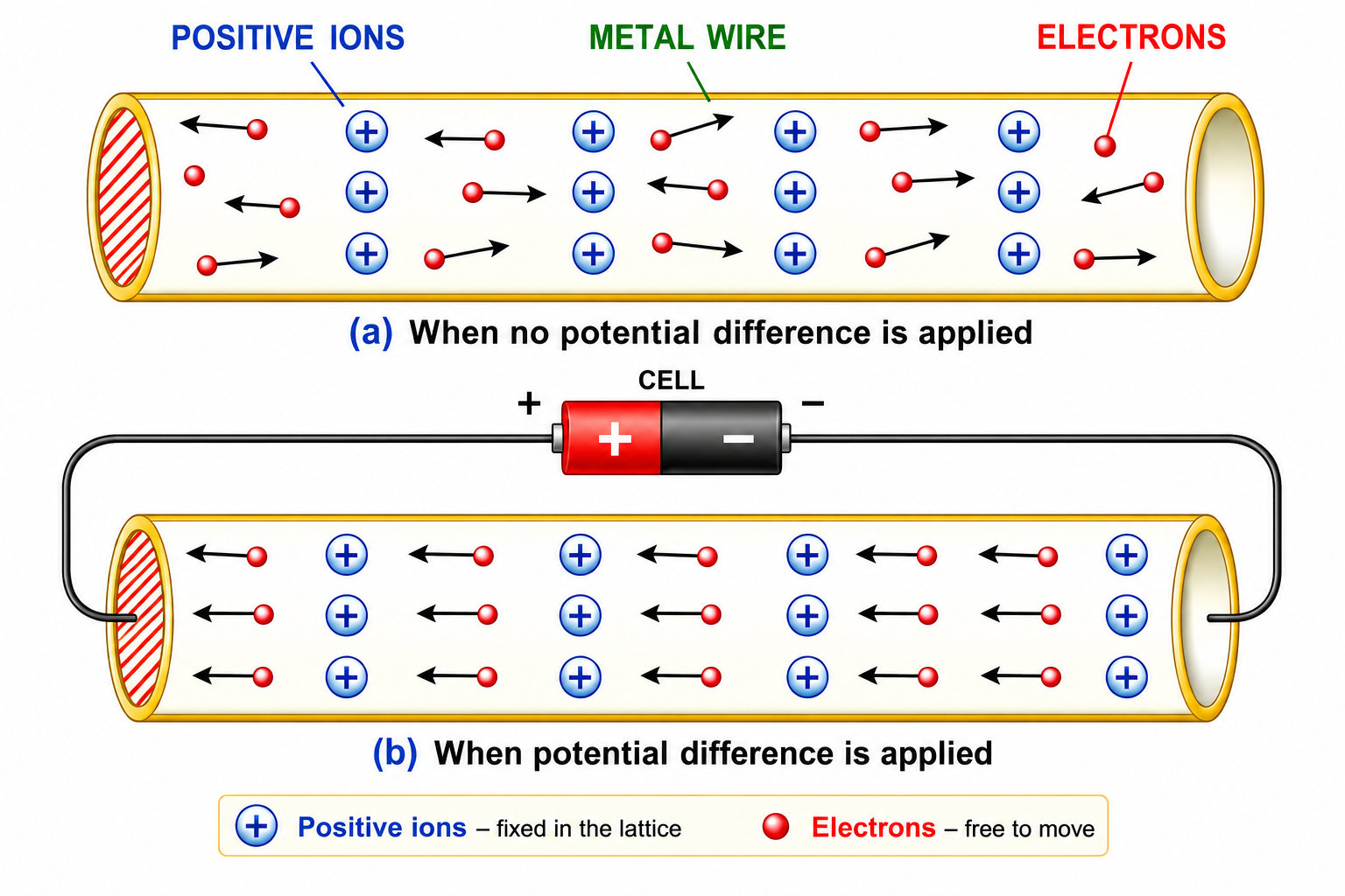
A metal conductor contains fixed positive ions and free electrons.
When no potential difference is applied across the wire, free electrons move at random, colliding among themselves and with fixed positive ions [Textbook Fig. 8.2 (a)].
(a) Electrons move randomly when no P.D. is applied. (b) With P.D., electrons drift towards the positive terminal, continuously colliding with fixed positive ions (Resistance).
When a potential difference is applied, electrons accelerate towards the positive potential end [Textbook Fig. 8.2 (b)]. During movement, they collide continuously with fixed positive ions and lose kinetic energy.
This continuous collision of moving electrons with fixed positive ions constitutes the resistance of the conductor.
5. Ohm's Law ($V = IR$)
OHM'S LAW
Statement: At constant temperature, the electric current flowing through a conductor is directly proportional to the potential difference applied across its ends.
$$ V \propto I \implies V = I R $$
Where $R$ is the constant of proportionality called Resistance.
SI Unit of Resistance: Ohm ($\Omega$) — named after Georg Simon Ohm.
Definition of 1 Ohm ($1\ \Omega$): The resistance of a conductor is 1 $\Omega$ if a potential difference of 1 V causes a current of 1 A to flow through it ($1\ \Omega = 1\text{ V A}^{-1}$).
Conductance: Reciprocal of resistance ($\text{Conductance} = 1/R$). Unit: $\Omega^{-1}$, siemen ($\text{S}$), or mho.
6. Experimental Verification of Ohm's Law
Circuit Setup [Textbook Fig. 8.4]: Rheostat ($Rh$), key ($K$), ammeter ($A$), and resistance wire ($R$) connected in series with battery ($B$). Voltmeter ($V$) connected in parallel across $R$.
Left: Ammeter in series measures $I$; Voltmeter in parallel measures $V$; Rheostat adjusts current. Right: Straight line $V$-$I$ graph passing through origin verifies $V \propto I$.
Observation: Changing rheostat settings produces proportional changes in $V$ and $I$. The ratio $\frac{V}{I}$ remains constant, verifying Ohm's law.
Limitation: Ohm's law holds only when the temperature of the conductor remains constant.
7. $V$-$I$ Graph and Determination of Resistance
V-I Graph Key Conclusions
Key Conclusions from V-I Graph:
Left: Ohmic conductors show a linear relationship ($V \propto I$). Right: Non-ohmic conductors show a non-linear curve.
The graph is a straight line passing through the origin → verifies Ohm's Law ($V \propto I$).
Slope of V-I graph = Resistance ($R$). A steeper slope means higher resistance ($R = \frac{\Delta V}{\Delta I}$).
Slope of I-V graph = $1/R$ (conductance). A steeper slope means lower resistance ($\frac{1}{R} = \frac{\Delta I}{\Delta V}$).
8. Ohmic and Non-Ohmic Resistors
Property
Ohmic Resistor
Non-Ohmic Resistor
Ohm's Law
Obeys Ohm's law ($V/I$ is constant).
Does NOT obey Ohm's law ($V/I$ is variable).
$V$-$I$ Graph Shape
Straight line passing through origin [Textbook Fig. 8.5].
Area of Cross-Section ($A$): $R \propto \frac{1}{A}$ (Thicker wire $\to$ less resistance. Doubling area halves resistance.)
Nature of Material ($\rho$): Different materials have different inherent resistances ($n$).
Temperature: For metals, resistance increases with temperature. For semiconductors and insulators, resistance decreases with temperature.
Since slope $= R$, a steeper slope at $T_1$ indicates that resistance increases at a higher temperature ($T_1 > T_2$).
10. Specific Resistance or Resistivity ($\rho$)
RESISTIVITY FORMULA
$$ R = \rho \frac{l}{A} \quad \implies \quad \rho = \frac{R A}{l} $$
Where $\rho$ (rho) = Resistivity or Specific Resistance of the material.
SI unit of Resistivity: Ohm-metre ($\Omega\cdot\text{m}$).
Definition of $\rho$: Specific resistance of a material is the resistance of a wire of that material of unit length ($1 \text{ m}$) and unit area of cross-section ($1 \text{ m}^2$).
Important Rule: Specific resistance $\rho$ is a characteristic material property. It depends ONLY on material and temperature. It is INDEPENDENT of wire length or cross-sectional area!
11. Wire Stretching / Folding — Classic PYQ Topic
Wire Stretching Trick
Core Principle: When a wire is stretched or folded, its Volume remains constant ($V = l \times A = \text{constant}$).
Wire stretched to $n$ times length ($l' = n l$):
New area $A' = A/n$ (volume constant) $\implies R' = \rho \frac{n l}{A/n} = n^2 \rho \frac{l}{A} = n^2 R$. ∴ New Resistance $= n^2 R$ (increases by factor of $n^2$)
Wire folded in half ($l' = l/2$):
New area $A' = 2A$ (two wires in parallel) $\implies R' = \rho \frac{l/2}{2A} = \frac{R}{4}$. ∴ New Resistance $= R/4$ (decreases to one-fourth)
Specific Resistance ($\rho$):REMAINS UNCHANGED in both cases!
12. Choice of Material of Wire for Specific Purposes
Application
Material Used
Reason / Required Property
Connection Wires & Power Lines
Copper or Aluminium
Very small resistivity ($\rho \approx 1.7 \times 10^{-8} \ \Omega\cdot\text{m}$). Minimizes heat power loss ($I^2Rt$).
Standard Resistance Wires
Manganin or Constantan
High resistivity, and resistance remains unchanged with temperature.
Fuse Wire
Lead-Tin alloy
High resistivity and low melting point. Melts easily on current overload.
Filament of Electric Bulb
Tungsten wire
High melting point ($3380^\circ\text{C}$) and glows white hot without melting.
Heating Element
Nichrome wire
High resistivity, high melting point, non-oxidizing at red heat.
13. Superconductors
Superconductor: A substance of zero resistance (infinite conductance) at very low critical temperature $T_c$. Examples: Mercury below $4.2\text{ K}$, Lead below $7.25\text{ K}$, Niobium below $9.2\text{ K}$.
PART (B): Electromotive Force (E.M.F.), Terminal Voltage, Internal Resistance & Resistors Combination
1. Electromotive Force (E.M.F.) of a Cell ($\mathcal{E}$)
Electromotive Force ($\mathcal{E}$): Potential difference between cell terminals when no current is drawn (OPEN CIRCUIT [Textbook Fig. 8.11]).
Open circuit: No current flows ($I=0$). The voltmeter measures the true Electromotive Force ($\mathcal{E}$).
FORMULA: E.M.F.
$$ \mathcal{E} = \frac{W}{q} $$
Where $W$ = work done taking charge around complete circuit, $q$ = charge.
SI Unit: Volt ($\text{V}$).
Factors Affecting E.M.F.: (1) Material of electrodes, (2) Nature of electrolyte. Independent of electrode shape, size, or distance.
2. Terminal Voltage ($V$) and Voltage Drop ($v$)
Terminal Voltage ($V$): Potential difference across cell terminals when current is drawn (CLOSED CIRCUIT [Textbook Fig. 8.12]). $V = W'/q$.
Voltage Drop ($v$): Work done per unit charge in driving test charge through electrolyte inside cell. $v = w/q$.
Closed circuit: Current $I$ flows. Voltmeter reads the Terminal Voltage $V$, which is less than $\mathcal{E}$ due to the voltage drop $v = Ir$ across internal resistance.
FORMULA: CELL VOLTAGE RELATION
$$ \mathcal{E} = V + v \quad \implies \quad V = \mathcal{E} - v = \mathcal{E} - I r $$
Terminal voltage $V$ is less than e.m.f. $\mathcal{E}$ during cell discharge by voltage drop $v = Ir$.
3. Comparison: E.M.F. vs Terminal Voltage
E.M.F. ($\mathcal{E}$) of a Cell
Terminal Voltage ($V$) of a Cell
Work done in moving unit charge in complete circuit (inside + outside cell).
Work done in moving unit charge in external circuit outside cell.
Characteristic property of cell (independent of current drawn).
Depends on current drawn from cell ($V = \mathcal{E} - Ir$).
Greater than terminal voltage during discharging.
Less than e.m.f. during discharging.
4. Internal Resistance of a Cell ($r$)
Internal Resistance ($r$): Resistance offered by the electrolyte inside the cell to the flow of current (ions).
The cell (dashed box) has EMF $\mathcal{E}$ and internal resistance $r$. It drives current $I$ through external resistance $R$. Total resistance $= R + r$.
FORMULA: INTERNAL RESISTANCE
$$ I = \frac{\mathcal{E}}{R + r} \quad \text{and} \quad r = \frac{\mathcal{E} - V}{I} = \left(\frac{\mathcal{E}}{V} - 1\right) R $$
Temperature: Higher temperature $\to$ LESS internal resistance.
6. Combination of Resistors in Series
Resistors are connected end-to-end so that the same current flows through all of them [Textbook Fig. 8.15].
Same current $I$ flows through every resistor in series. Voltage divides: $V = V_1 + V_2 + V_3$. Equivalent Resistance $R_s = R_1 + R_2 + R_3$.
Quantity
Behaviour in Series
Current ($I$)
Same through every resistor: $I = I_1 = I_2 = I_3$
Voltage ($V$)
Divides: $V = V_1 + V_2 + V_3$
Equivalent Resistance
$R_s = R_1 + R_2 + R_3 + \dots$ (Always greater than largest individual R)
DERIVATION: SERIES
$$ V = V_1 + V_2 + V_3 $$
$$ I R_s = I R_1 + I R_2 + I R_3 \quad (\text{since } I \text{ is same, cancel } I) $$
$$ \mathbf{R_s = R_1 + R_2 + R_3} $$
7. Combination of Resistors in Parallel
Resistors are connected between the same two points (nodes) so that the same voltage appears across all of them [Textbook Fig. 8.16].
Same voltage $V$ across every resistor in parallel. Main current divides: $I = I_1 + I_2 + I_3$. Equivalent Resistance $\frac{1}{R_p} = \frac{1}{R_1} + \frac{1}{R_2} + \frac{1}{R_3}$.
8. Special Branching Formulas (Current & Voltage Division)
Current Division in Parallel [Textbook Fig. 8.19]:
$$I_1 = \left(\frac{R_2}{R_1 + R_2}\right) I \quad \text{and} \quad I_2 = \left(\frac{R_1}{R_1 + R_2}\right) I$$
The V-I slope indicates resistance. Series combination has higher effective resistance than parallel, hence a steeper slope. Voltage divides in series, while current divides in parallel.
Voltage Division in Series [Textbook Fig. 8.20]:
$$V_1 = \left(\frac{R_1}{R_1 + R_2}\right) V \quad \text{and} \quad V_2 = \left(\frac{R_2}{R_1 + R_2}\right) V$$
V-I Graph Slope [Textbook Fig. 8.18]: Series line has steeper slope than parallel line ($R_s > R_p$).
PART (C): Electrical Energy and Power
1. Electrical Energy ($W$)
FORMULA: ELECTRICAL ENERGY
$$\mathbf{W = V I t = I^2 R t = \frac{V^2}{R} t \quad (\text{Joules})}$$
2. Heating Effect of Current & Joule's Law of Heating
FORMULA: JOULE'S LAW OF HEATING
$$H = I^2 R t \text{ Joules} \quad \implies \quad H = \frac{I^2 R t}{4.186} \approx 0.24 I^2 R t \text{ calories}$$
5. Power Rating of Electrical Appliances & Safe Current
Appliance Power Rating
Appliance Power Rating Formulas ($100\text{ W}-220\text{ V}$):
Resistance of Appliance Filament ($R$): $R = \frac{V_{\text{rated}}^2}{P_{\text{rated}}}$.
Safe Limit of Current ($I_{\text{safe}}$): $I_{\text{safe}} = \frac{P_{\text{rated}}}{V_{\text{rated}}}$.
Bulb Brightness in Parallel: $100\text{ W}$ bulb glows brighter than $10\text{ W}$ bulb ($P = V^2/R$).
Bulb Brightness in Series: $10\text{ W}$ bulb glows brighter than $100\text{ W}$ bulb ($P = I^2R$, as $R_{10\text{W}} > R_{100\text{W}}$).
6. Calculation of Household Electrical Energy & Bill
MONTHLY BILL FORMULA
$$\mathbf{\text{Energy (in kWh)} = \frac{\text{Power (in Watt)} \times \text{Time (in Hour)}}{1000}}$$
$$\mathbf{\text{Total Cost} = \text{Electrical Energy (in kWh)} \times \text{Cost per kWh}}$$
PART (D): Solved Numerical Examples Masterclass
✍ SOLVED EXAMPLE 1
Q. When a potential difference of $2\text{ V}$ is applied across a wire of length $5\text{ m}$, a current of $1\text{ A}$ flows through it. Calculate: (i) resistance per unit length of wire, (ii) resistance of $2\text{ m}$ length of wire, (iii) resistance across the ends of wire if it is doubled on itself.
Q. A high resistance voltmeter measures the potential difference across a battery to be $9.0\text{ V}$. On connecting a $24 \ \Omega$ resistor across the terminals of battery, the voltmeter reads $7.2\text{ V}$. Calculate internal resistance of battery.
Q. A battery of e.m.f. $9\text{ V}$ and internal resistance $0.6 \ \Omega$ is connected to three resistors $A (2 \ \Omega)$, $B (4 \ \Omega)$, and $C (6 \ \Omega)$ where $B$ and $C$ are in parallel and in series with $A$. Calculate: (a) combined resistance of B and C, (b) total circuit resistance, (c) main current, (d) current in resistor B and C, (e) voltage drop inside cell, (f) terminal voltage of cell.
(a) Parallel Resistance of B & C: $R_p = \frac{4 \times 6}{4 + 6} = \frac{24}{10} = \mathbf{2.4 \ \Omega}$.
(c) Main Current: $I = \frac{\mathcal{E}}{R_{\text{total}}} = \frac{9}{5.0} = \mathbf{1.8\text{ A}}$. Current in A is $1.8\text{ A}$.
(d) Current in B & C: $I_B = \left(\frac{6}{4+6}\right) \times 1.8 = \mathbf{1.08\text{ A}}$. Current in C: $I_C = 1.8 - 1.08 = \mathbf{0.72\text{ A}}$.
(e) Voltage Drop inside Cell: $v = I r = 1.8 \times 0.6 = \mathbf{1.08\text{ V}}$.
Q. A house uses 2 bulbs of $100\text{ W}$ each and 2 fans of $60\text{ W}$ each for an average of $10\text{ hours}$ each day. Calculate (a) energy consumed in a month of 30 days in $\text{kWh}$, (b) total cost of electricity at ₹ 4.50 per unit.

 VARDAAN COMET