
Definition: A lens is a transparent refracting medium bounded by either the two spherical surfaces or one surface spherical and other surface plane.
A plane surface can be treated as a spherical surface of infinite radius of curvature.
Lenses are of two kinds:
(1) Converging or convex lens: A convex lens is thick in its middle and thin at the periphery. A light beam converges on passing through such a lens, so it is also called the converging lens.
A convex lens may be of the following three kinds:
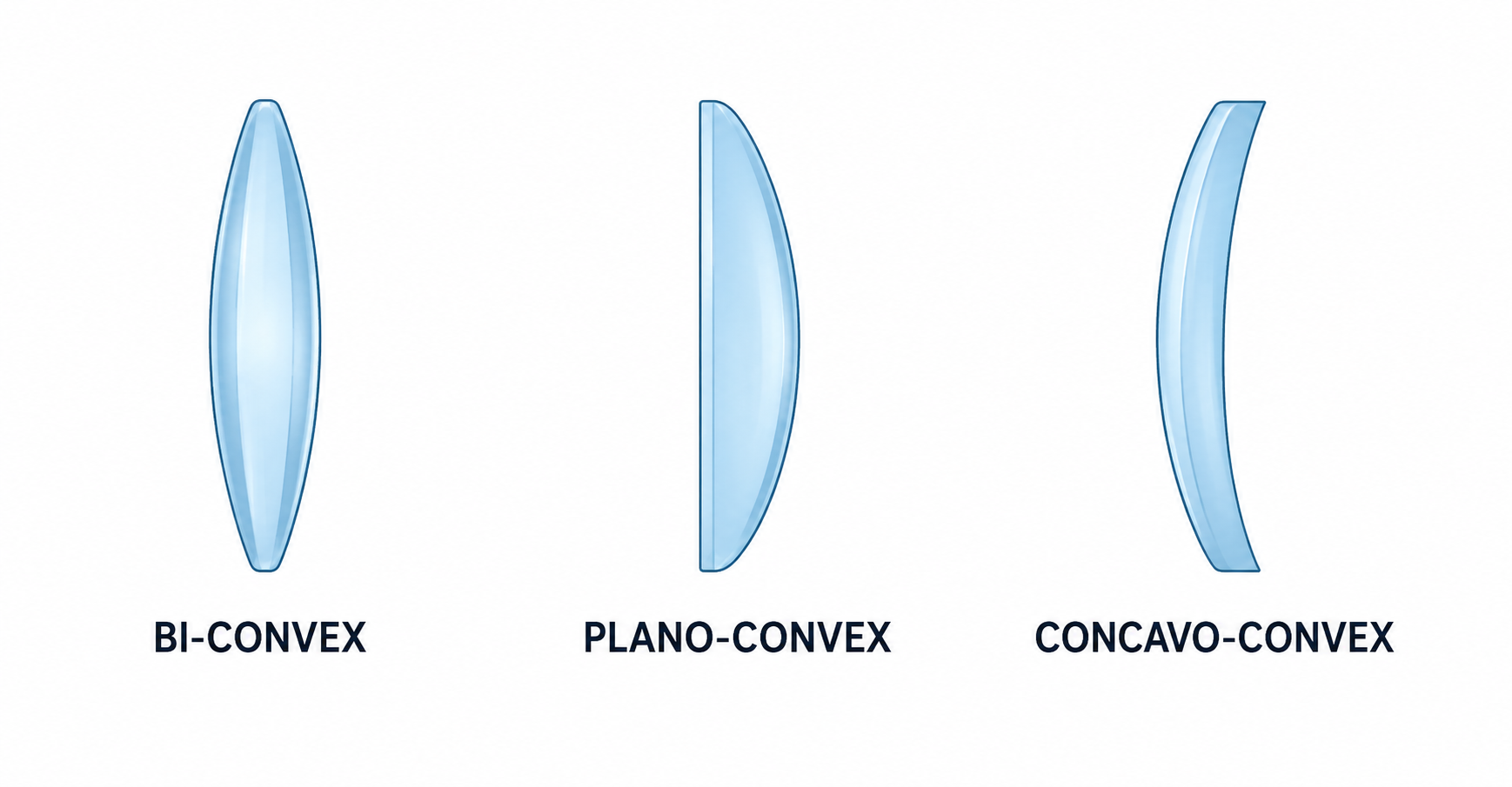
Fig. 5.1 Convex lenses
(2) Diverging or concave lens: A concave lens is thick at its periphery and thin in the middle. Such a lens diverges the light rays incident on it, so it is also called the diverging lens.
A concave lens may be of the following three kinds:
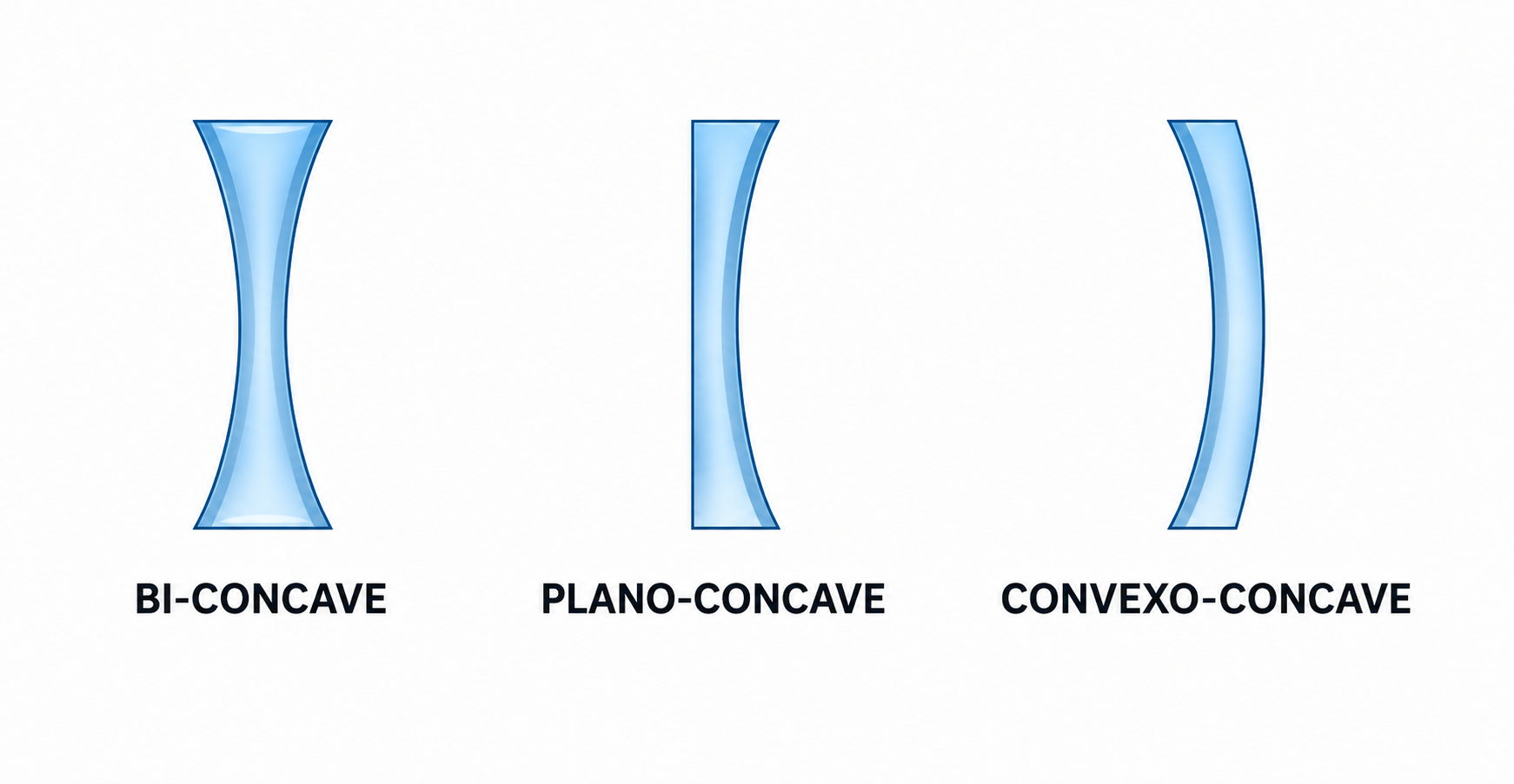
Fig. 5.2 Concave lenses
The refraction of light through a lens can be understood in a simple way by considering a lens as being made up of a set of prisms. The central portion of the lens may be treated as a rectangular slab, with prisms on either side of it.
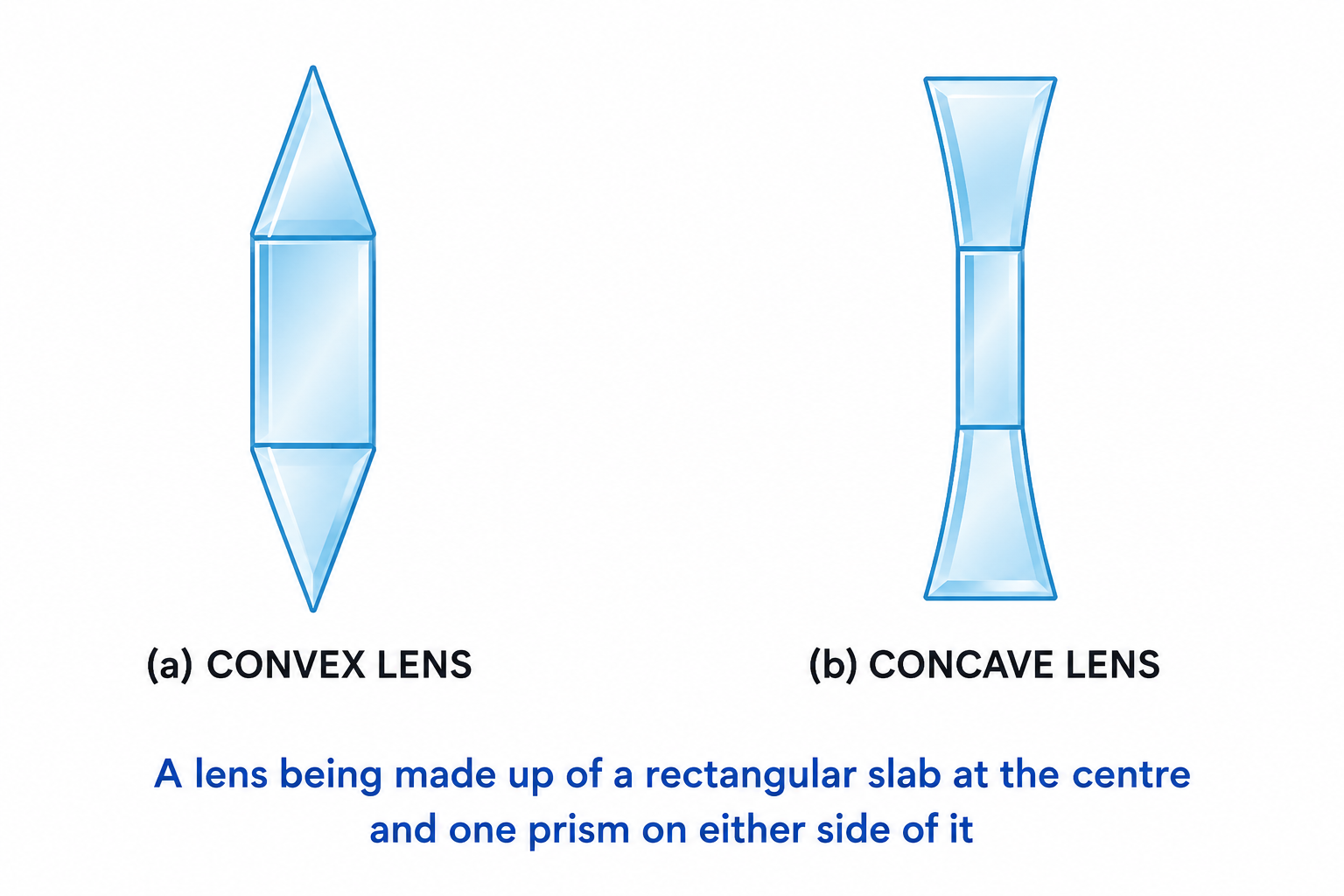
Fig. 5.4 A lens being made up of a rectangular slab at the centre and one prism on either side of it
In a convex lens, the upper part acts like a prism with its base downwards, and the lower part acts like a prism with its base upwards. Rays incident on the upper prism bend downwards towards its base, while rays on the lower prism bend upwards. The central part acts as a parallel-sided glass slab, passing rays undeviated. Thus, the set of prisms forming a convex lens converges parallel rays to a point $F$.
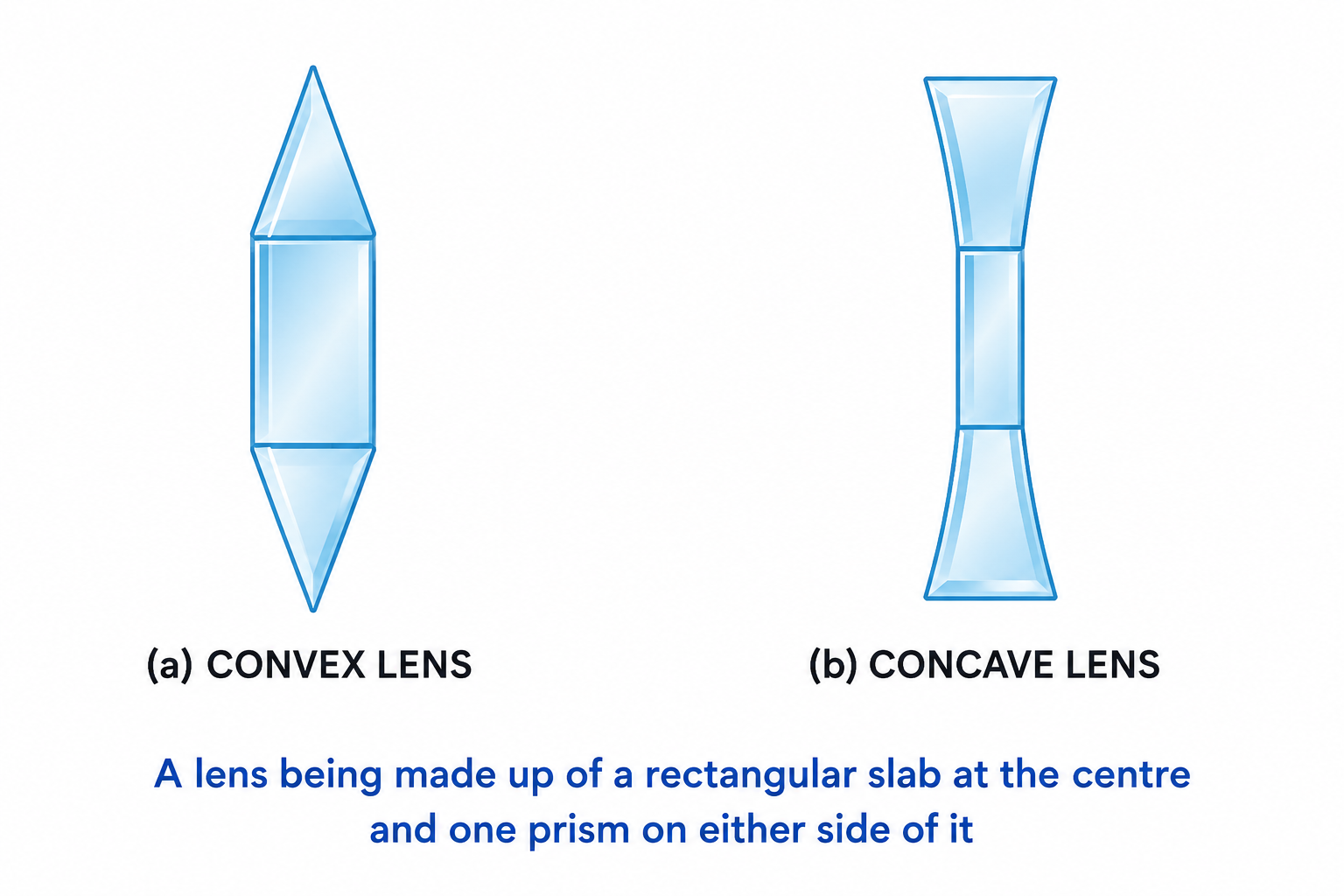
Fig. 5.5 Convergent action of a convex lens
In a concave lens, the upper part acts like a prism with its base upwards, bending rays upwards. The lower part acts like a prism with its base downwards, bending rays downwards. The central part passes rays undeviated. Thus, a concave lens diverges parallel rays as if they are coming from a common point $F$.
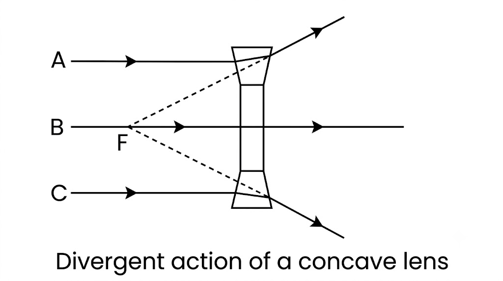
Fig. 5.6 Divergent action of a concave lens
.png)
Fig. 5.9 Optical centre (thin lens)
A light ray can enter a lens from either side, therefore, a lens has two principal foci situated at equal distances from the optical centre on either side. These are known as the first focal point ($F_1$) and the second focal point ($F_2$).
First focal point ($F_1$): For a convex lens, it is a point on the principal axis such that the rays of light coming from it, after refraction through the lens, become parallel to the principal axis. For a concave lens, it is a point on the principal axis such that the incident rays of light appearing to meet at it, after refraction become parallel to the principal axis.
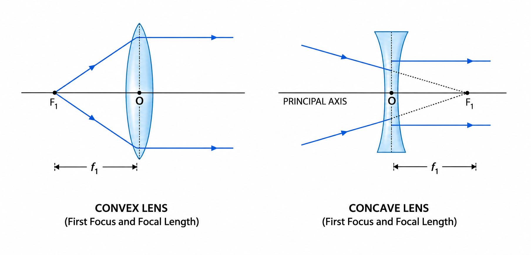
Fig. 5.10 First focus and focal length
Second focal point ($F_2$): For a convex lens, it is a point on the principal axis such that the rays of light incident parallel to the principal axis, after refraction from the lens, pass through it. For a concave lens, it is a point on the principal axis such that the rays of light incident parallel to the principal axis, after refraction from the lens, appear to be diverging from this point.
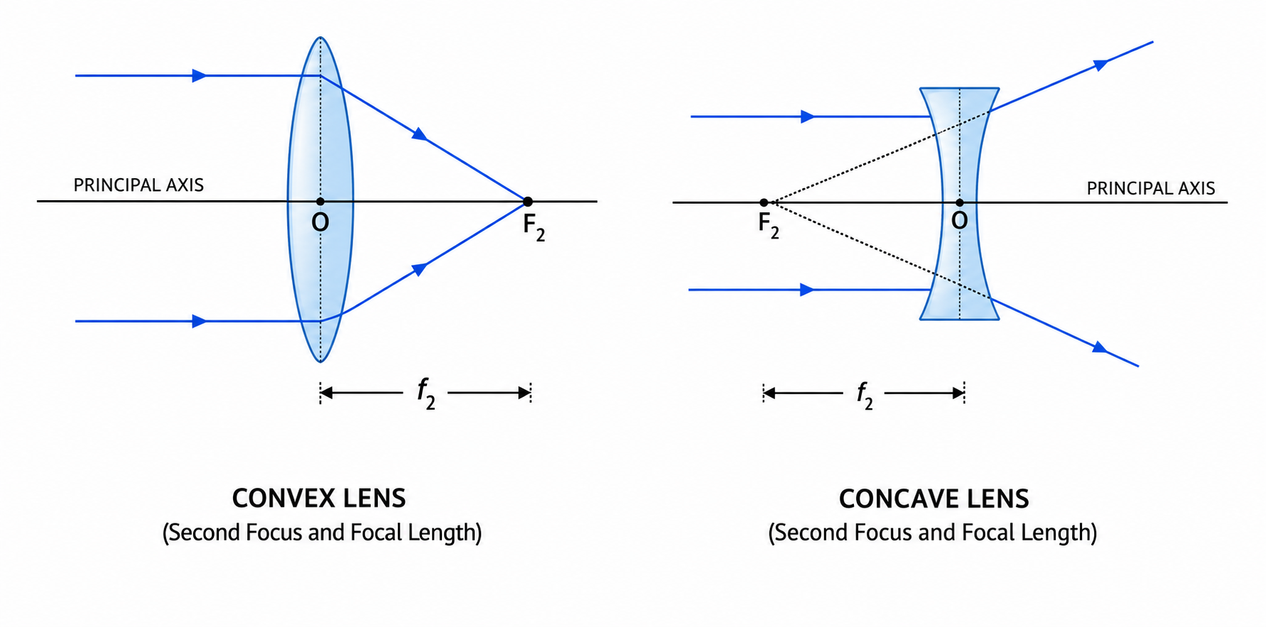
Fig. 5.11 Second focus and focal length
A ray of light bends towards the normal when entering the lens from air to glass, and bends away from the normal when emerging from glass to air. For ray diagrams, we consider the lens to be thin and show the net bending at the straight vertical line passing through the optical centre.
The position, size and nature of the image of an object formed by a lens, can be determined by drawing a ray diagram. We use any two of the following three principal rays:
Case (i): When the object is at infinity ($u = \infty$)
The rays coming from an object at infinity are parallel to each other. The image is formed at the focus on the other side. It is (a) real, (b) inverted, and (c) highly diminished (almost a point).
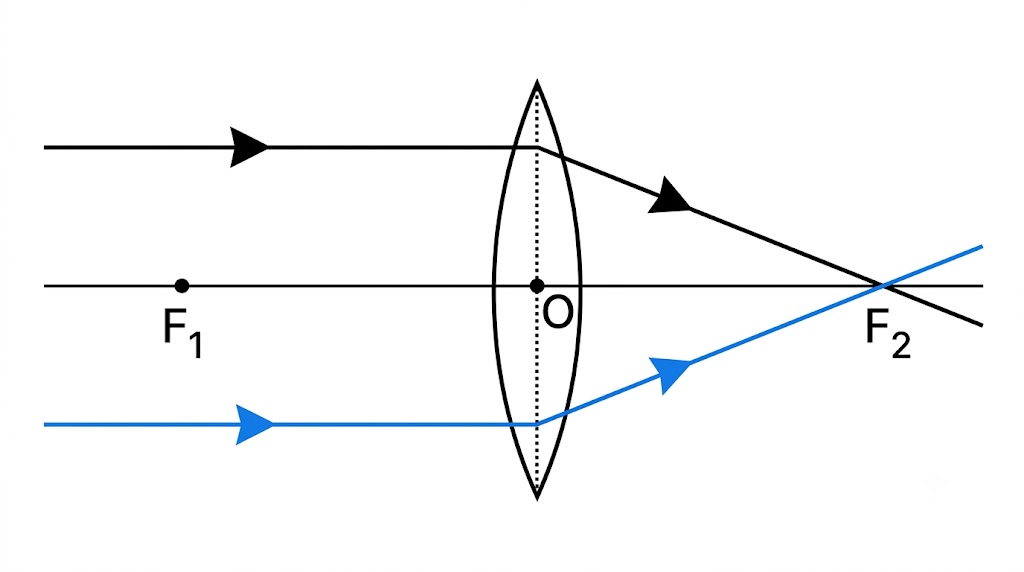
Fig. 5.30 Image formation by a convex lens for an object at infinity
Case (ii): When the object is beyond $2F_1$ ($u > 2f$)
The image is formed between $F_2$ and $2F_2$ on the other side. It is (a) real, (b) inverted, and (c) diminished.
Application: Used in a camera lens.
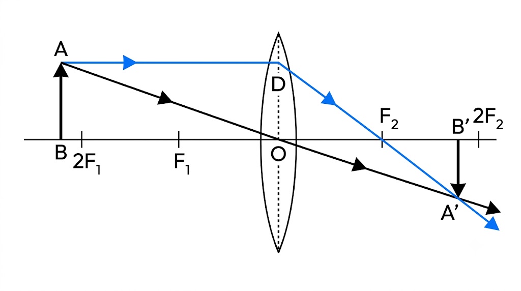
Fig. 5.32 Image formation by a convex lens for the object beyond $2F_1$
Case (iii): When the object is at $2F_1$ ($u = 2f$)
The image is formed at $2F_2$ on the other side. It is (a) real, (b) inverted, and (c) of the same size as the object.
Application: Used in a terrestrial telescope for erecting the inverted image.
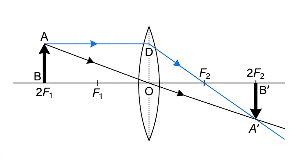
Fig. 5.33 Image formation by a convex lens for the object at $2F_1$
Case (iv): When the object is between $F_1$ and $2F_1$ ($f < u < 2f$)
The image is formed beyond $2F_2$ on the other side. It is (a) real, (b) inverted, and (c) magnified.
Application: Used in cinema and slide projectors.
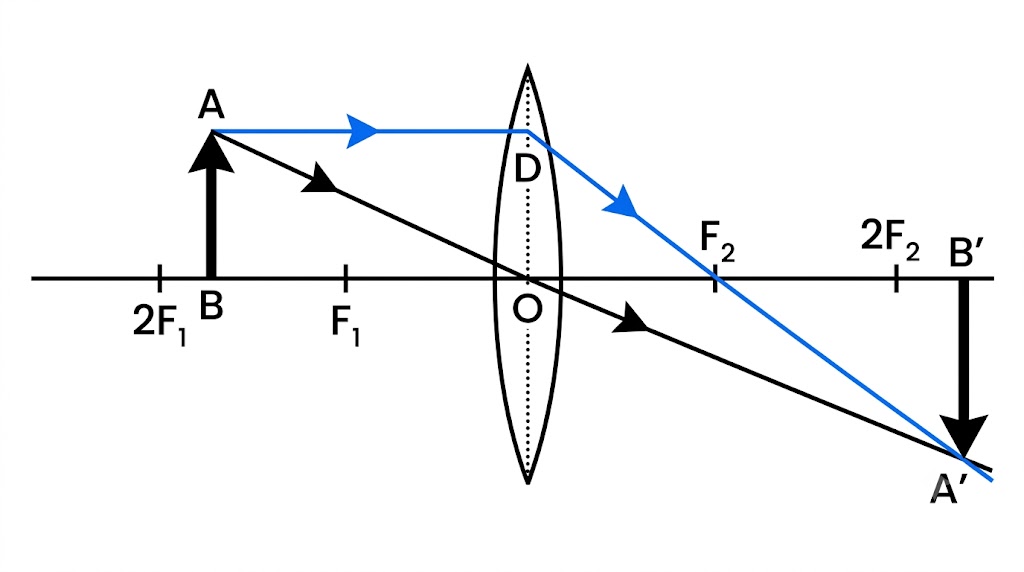
Fig. 5.34 Image formation by a convex lens for the object between $F_1$ and $2F_1$
Case (v): When the object is at $F_1$ ($u = f$)
The image is formed at infinity on the other side. It is (a) real, (b) inverted, and (c) highly magnified.
Application: Used in the collimator of a spectrometer.
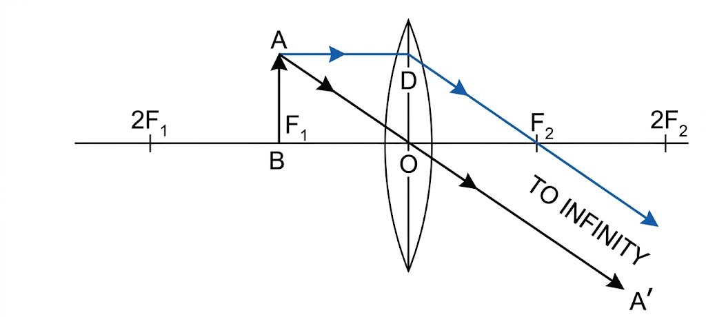
Fig. 5.35 Image formation by a convex lens for the object at $F_1$
Case (vi): When the object is between the lens and focus ($u < f$)
The image is formed on the same side and behind the object. It is (a) virtual, (b) erect or upright, and (c) magnified.
Application: Used as a reading lens (magnifying glass) or simple microscope.
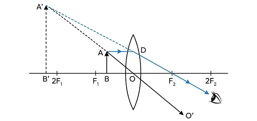
Fig. 5.36 Image formation by a convex lens for the object between the optical centre and the focus
Case (i): When the object is at infinity
The rays parallel to the principal axis after refraction from the concave lens, appear to diverge from the second focus $F_2$. Thus a virtual, erect and highly diminished image is formed at the focus.
Application: Galilean telescope.
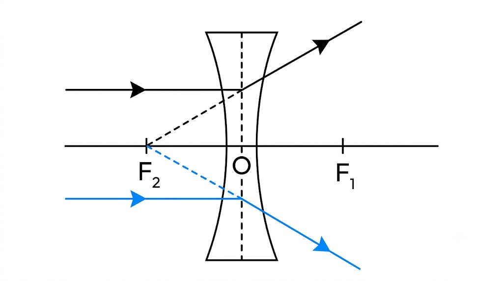
Fig. 5.37 Ray diagram for image formation by a concave lens when the object is at infinity
Case (ii): When the object is at any finite distance from the concave lens
The image is formed between the lens and focus, on the same side of the object. It is (a) virtual, (b) erect, and (c) diminished.
Application: Used in spectacles for short-sighted persons (Myopic eye).
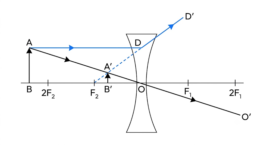
Fig. 5.39 Ray diagram for image formation by a concave lens when the object is between infinity and the lens
| Image by a convex lens | Image by a concave lens |
|---|---|
| 1. The image can be real as well as virtual. It is real if the object lies beyond the focus, while it is virtual if the object lies before the focus. | 1. The image is always virtual for all positions of object. |
| 2. The image can be magnified, of same size as well as diminished. | 2. The image is always diminished. |
| 3. The image can be inverted as well as erect. | 3. The image is always erect. |
We follow the cartesian sign convention to measure distances in a lens:
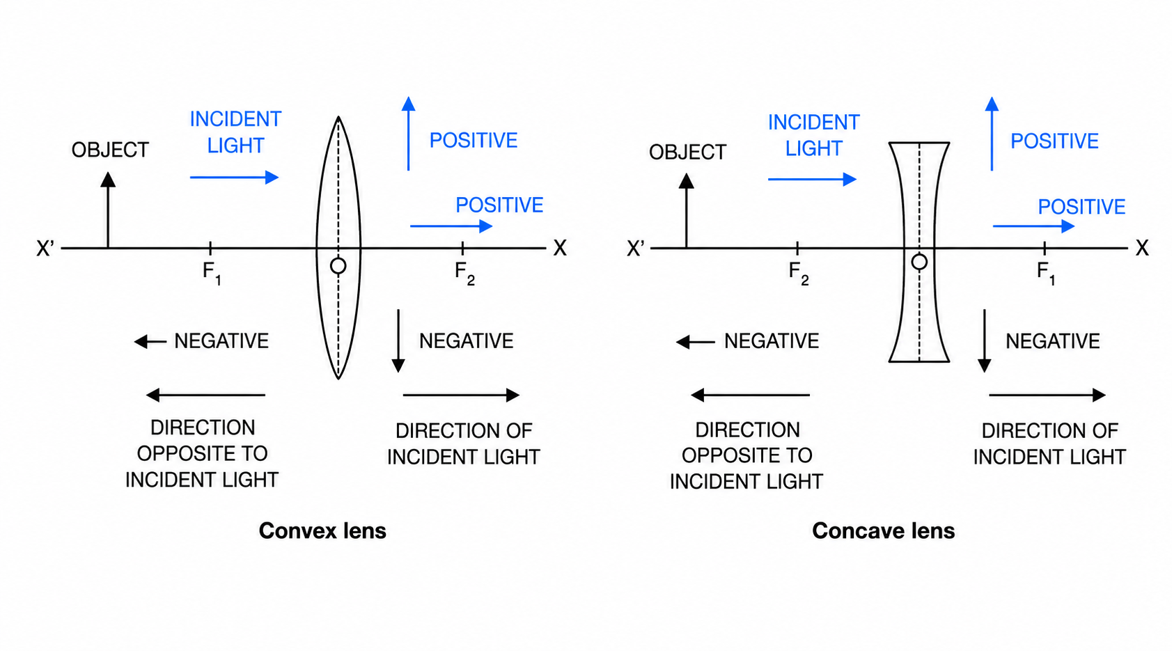
Fig. 5.52 Sign convention
The equation relating the distance of object ($u$), distance of image ($v$) and focal length ($f$) of a lens is called the lens formula. It is the same for both convex and concave lenses:
$$ \frac{1}{v} - \frac{1}{u} = \frac{1}{f} $$For Real image: $m$ is negative. For Virtual image: $m$ is positive.
APPLICATION A slide projector has to project a 100 times magnified image on a screen 5m away. What lens should be used?
Solution:
1. Image is Real (on screen), so $m = -100$. $v = +500 \text{ cm}$.
2. $m = v/u \implies -100 = 500/u$
$\implies u = -5 \text{ cm}$.
3. $\frac{1}{f} = \frac{1}{v} - \frac{1}{u} = \frac{1}{500} - \frac{1}{-5} = \frac{1}{500} + \frac{100}{500} = \frac{101}{500}$.
$f \approx 4.95 \text{ cm}$ (Convex Lens).
NUMERICAL An object is placed 20 cm from a convex lens of focal length 15 cm. Find image position.
Solution:
$u = -20$, $f = +15$.
$\frac{1}{v} - \frac{1}{u} = \frac{1}{f} \implies \frac{1}{v} = \frac{1}{15} - \frac{1}{20} = \frac{4-3}{60} = \frac{1}{60}$.
$v = +60 \text{ cm}$ (Real image on other side).
NUMERICAL An object is placed 30 cm from a concave lens of focal length 15 cm. Find image position.
Solution:
$u = -30$, $f = -15$.
$\frac{1}{v} - \frac{1}{u} = \frac{1}{f} \implies \frac{1}{v} = \frac{1}{-15} - \frac{1}{-30} = -\frac{1}{15} - \frac{1}{30} = \frac{-2-1}{30} = -\frac{3}{30} = -\frac{1}{10}$.
$v = -10 \text{ cm}$ (Virtual image on same side).
Definition: The deviation of the incident light rays produced by a lens on refraction through it, is a measure of its power. A thick lens (short focal length) deviates rays more and has more power.
$ \text{Power of lens (in D)} = \frac{1}{\text{focal length (in metre)}} $The unit of power is dioptre (symbol D). A lens is of power 1 D if its focal length is 1 m (or 100 cm).
Depending on the direction in which a lens deviates the light ray, its power is either positive or negative:
Note: If two thin lenses are placed in contact, the combination has a power equal to the algebraic sum of the powers of the individual lenses ($P = P_1 + P_2$).
Principle: To observe a tiny object distinctly, it is necessary to place it at the least distance of distinct vision ($D = 25 \text{ cm}$) from the normal eye. A magnifying glass is a convex lens of short focal length. When an object is placed within its focal length, it forms an erect, virtual, and magnified image on the same side, at a distance D.
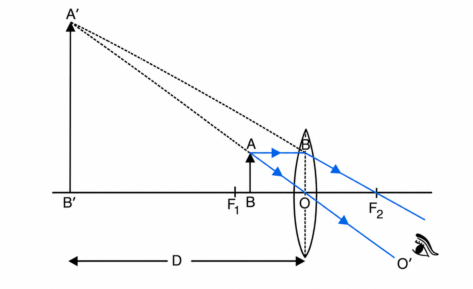
Fig. 5.56 Ray diagram for location of image in a magnifying glass
Where $f$ = focal length of the lens, $D$ = least distance of distinct vision (25 cm).
The magnifying power can be increased by using a lens of short focal length.
(1) Distant object method: Focus the image of a distant object (like a tree) on a screen (wall) using a convex lens. The distance between the lens and the screen gives the approximate focal length.
(2) Auxiliary plane mirror method: Place a plane mirror behind the convex lens. Adjust an object pin in front of the lens until its inverted image coincides with the pin itself without parallax. The distance of the pin from the lens is its exact focal length.
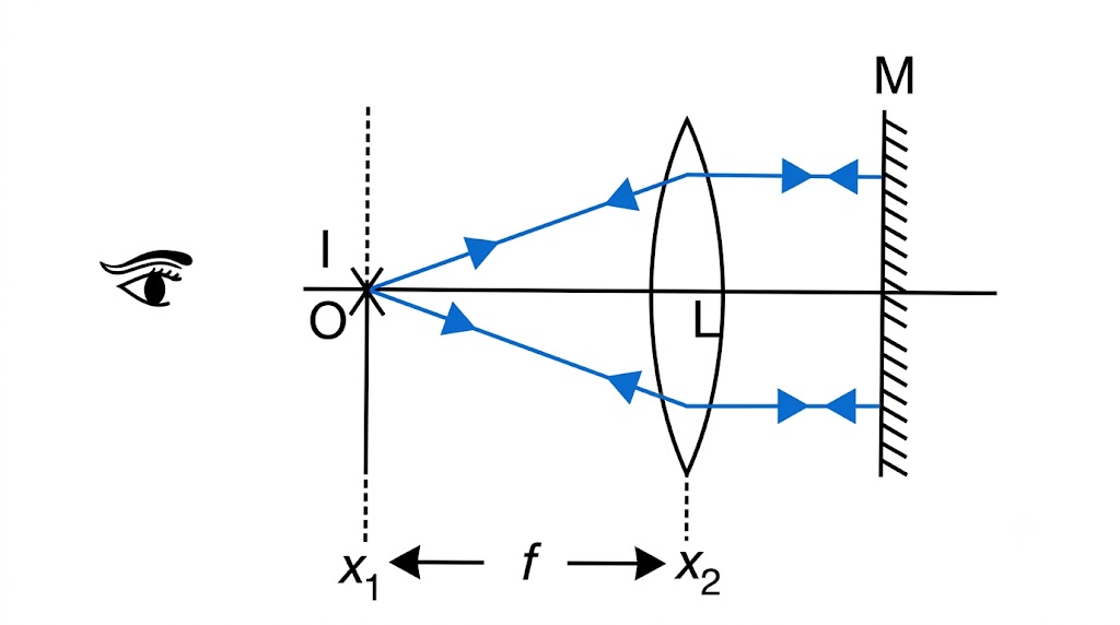
Fig. 5.61 Ray diagram for determination of focal length of a convex lens by using a pin and a plane mirror
| Method | Convex Lens | Concave Lens |
|---|---|---|
| By touching | Thick in the middle, thin at edges. | Thin in the middle, thick at edges. |
| By seeing the image (Near a printed page) | Letters appear magnified. | Letters appear diminished. |
| By seeing the image (Distant object) | Inverted image is seen. | Upright (erect) image is seen. |
 VARDAAN COMET