Vardaan Learning Institute
Class 12 Physics • High-Yield Rapid Revision Class Notes
🌐 vardaanlearning.com📞 9508841336
Chapter 9: Ray Optics and Optical Instruments
Exam Revision Capsule: A concise, highly condensed, and fully comprehensive master review sheet containing every core concept, derivation crux, key formula, ray diagram, and optical instrument needed for CBSE Board & Competitive Examinations.
1. Nature of Light & Reflection by Spherical Mirrors
- Visible Spectrum: Light wavelength $\lambda \approx 400\text{ nm}$ to $750\text{ nm}$ ($4000\text{ Å} - 7500\text{ Å}$). Speed in vacuum $\mathbf{c \approx 3 \times 10^8\text{ m s}^{-1}}$.
- Rectilinear Propagation: Because macroscopic apertures $\gg \lambda$, wave diffraction is negligible; light travels along straight rays.
- Laws of Reflection:
- Angle of incidence equals angle of reflection: $\mathbf{\angle i = \angle r'}$.
- Incident ray, reflected ray, and normal lie in the same plane at the point of incidence.
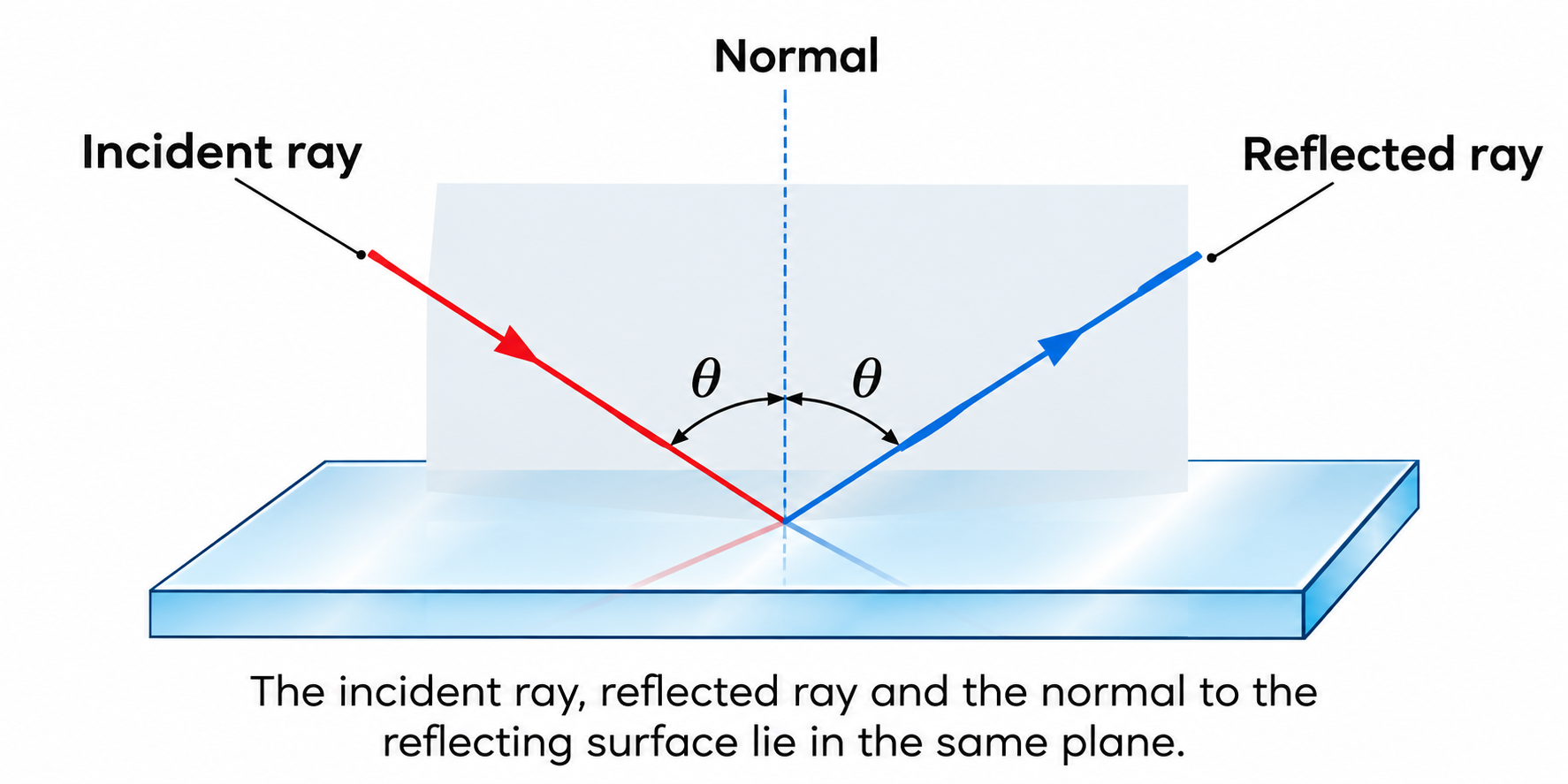
Figure 9.1: The incident ray, reflected ray, and normal lie in the same plane with \(\angle i = \angle r'\).
Cartesian Sign Convention (Must-Follow)
- Pole ($P$) of mirror (or optical center $O$ of lens) is the origin $(0,0)$.
- All distances measured in the direction of incident light (towards right) are positive (+ve).
- All distances measured opposite to incident light (towards left) are negative (-ve) $\implies$ For real object, $\mathbf{u < 0}$ always.
- Heights measured upward ($+y$) are positive (+ve); downward ($-y$) are negative (-ve).
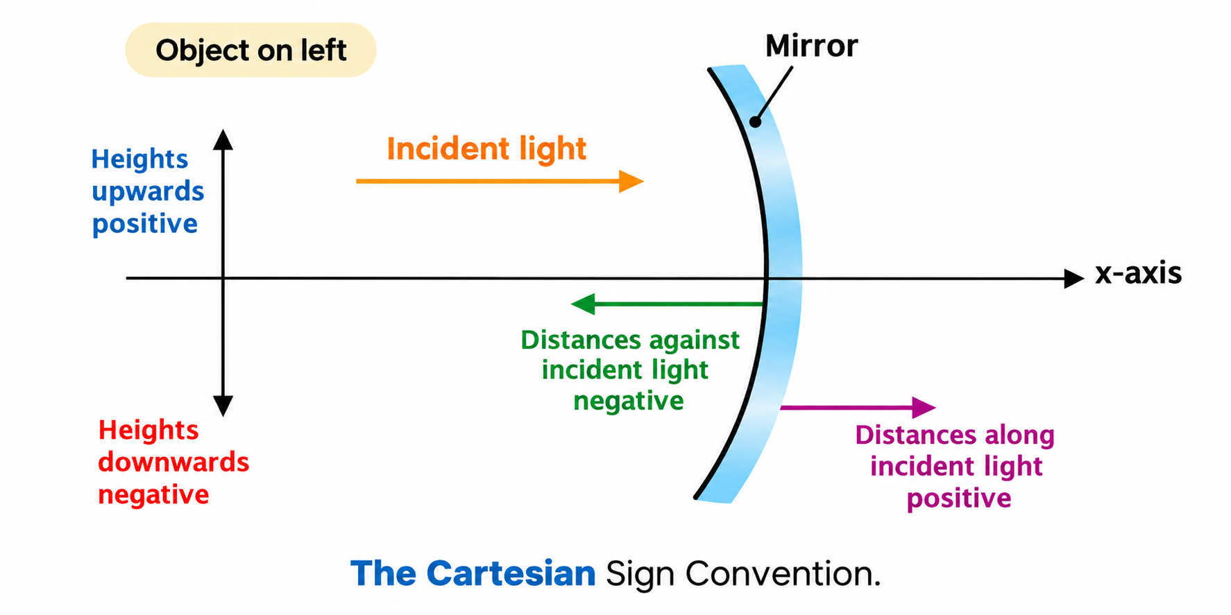
Figure 9.2: The Cartesian Sign Convention for spherical mirrors and lenses.
Principal Focus ($F$) & Focal Length ($f$)
- Concave Mirror: Parallel rays converge to a real focus in front of the mirror $\implies \mathbf{f < 0}$.
- Convex Mirror: Parallel rays appear to diverge from a virtual focus behind the mirror $\implies \mathbf{f > 0}$.
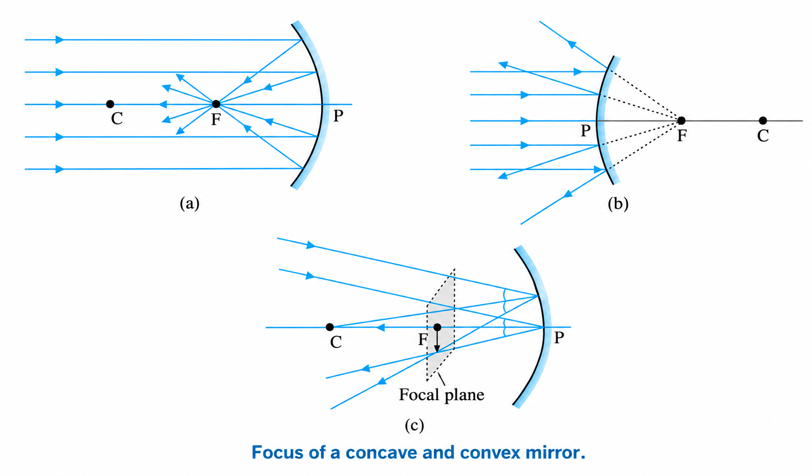
Figure 9.3: Focus of (a) concave mirror (real), (b) convex mirror (virtual), and (c) focal plane.
Derivation Crux: Focal Length & Radius of Curvature
From paraxial triangle geometry in Figure 9.4: $\tan \theta \approx \frac{MD}{CD} \approx \frac{MD}{R}$ and $\tan 2\theta \approx \frac{MD}{FD} \approx \frac{MD}{f}$.
For small angles, $2\theta \approx 2\left(\frac{MD}{R}\right) = \frac{MD}{f} \implies \mathbf{f = \frac{R}{2}}$.
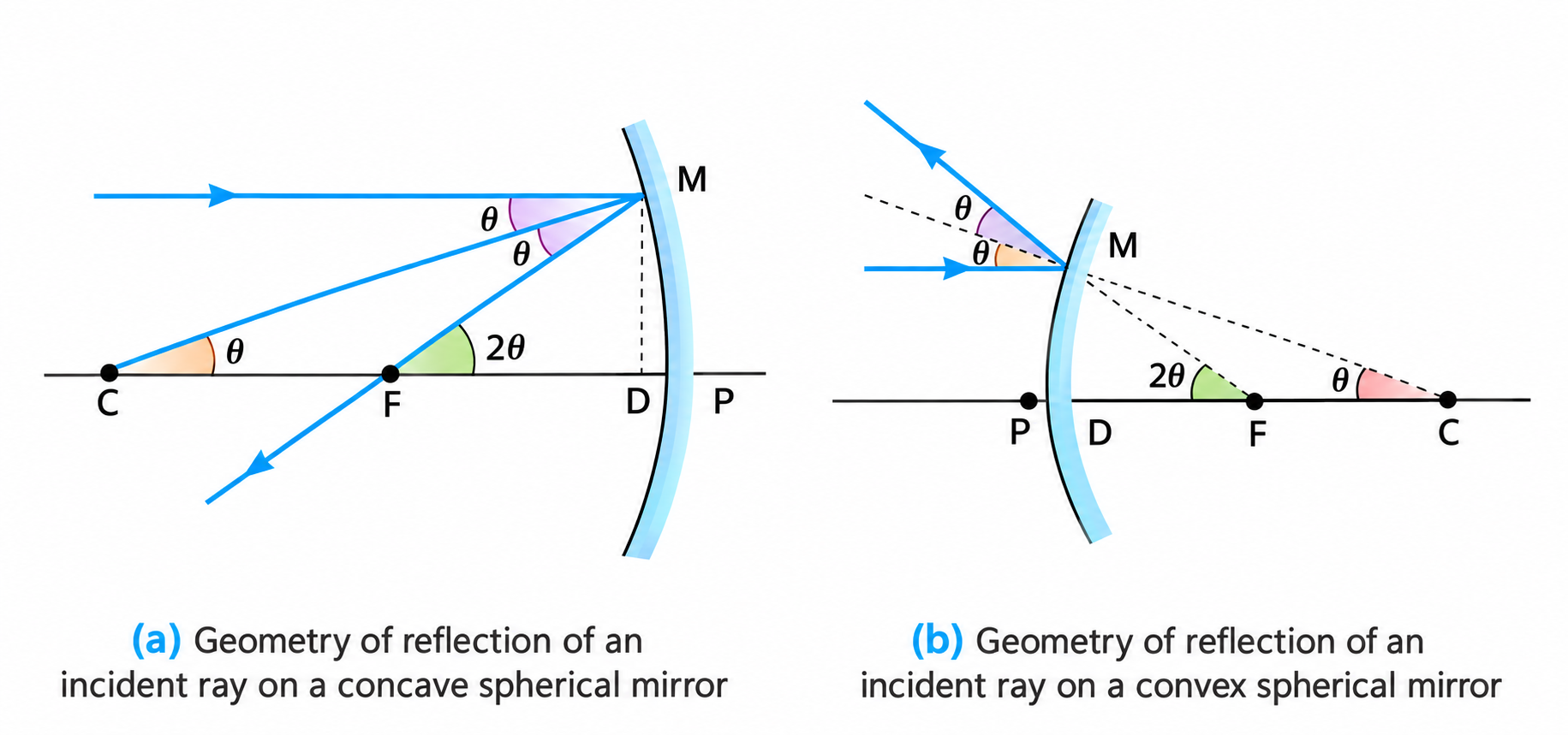
Figure 9.4: Geometry of reflection of an incident ray for deriving \(f = R/2\).
Derivation Crux: Mirror Equation & Magnification
From similar triangles $\triangle A'B'F \sim \triangle MPF$ and $\triangle A'B'P \sim \triangle ABP$ (Figure 9.5):
$$\frac{B'F}{FP} = \frac{B'P}{BP} \implies \frac{-v - (-f)}{-f} = \frac{-v}{-u} \implies \frac{v - f}{f} = \frac{v}{u}$$
Dividing throughout by $v$ yields the Mirror Formula:
$$\mathbf{\frac{1}{v} + \frac{1}{u} = \frac{1}{f}}$$
Linear Magnification: $\mathbf{m = \frac{h'}{h} = -\frac{v}{u} = \frac{f}{f - u} = \frac{f - v}{f}}$
Sign Guide: $m < 0 \implies$ Real & Inverted image; $m > 0 \implies$ Virtual & Erect image.
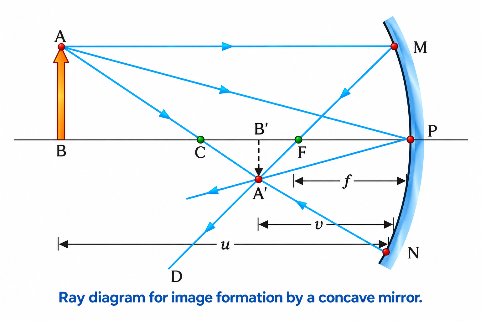
Figure 9.5: Ray diagram for image formation by a concave mirror (Mirror Equation Derivation).
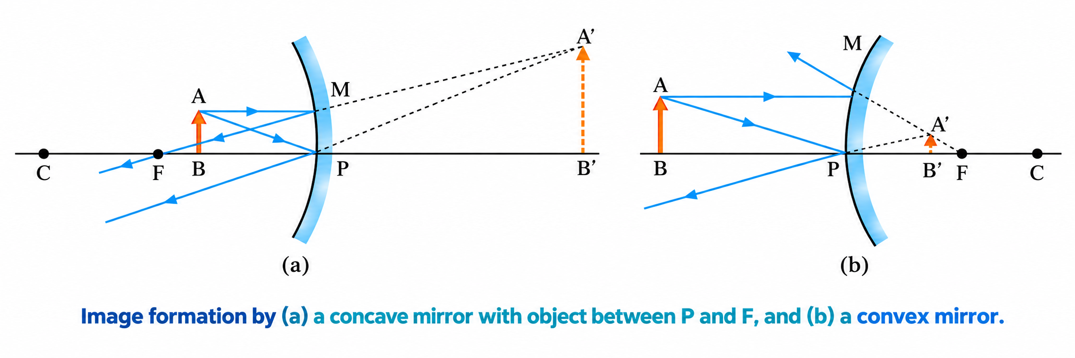
Figure 9.6: Virtual image formation: (a) concave mirror with \(u < f\) (magnified), (b) convex mirror (diminished).
Quick Summary: Image Formation by Mirrors
| Mirror Type |
Object Position |
Image Position |
Nature & Size |
Magnification ($m$) |
| Concave ($f < 0$) |
Beyond $C$ |
Between $C$ and $F$ |
Real, Inverted, Diminished |
$-1 < m < 0$ |
| At $C$ |
At $C$ |
Real, Inverted, Same Size |
$m = -1$ |
| Between $C$ and $F$ |
Beyond $C$ |
Real, Inverted, Magnified |
$m < -1$ |
| Between $P$ and $F$ |
Behind mirror |
Virtual, Erect, Magnified |
$m > +1$ |
| Convex ($f > 0$) |
Anywhere in front |
Between $P$ and $F$ behind |
Virtual, Erect, Diminished |
$0 < m < +1$ |
Exam Traps: Mirror Key Points
- Covering half of mirror: Complete image is still formed (every ray obeys laws of reflection). Only the intensity/brightness is reduced to half.
- Longitudinal Object (Phone): Since $m = -v/u$ varies continuously across the phone, longitudinal magnification $m_L = \frac{dv}{du} = -m^2$. The nearer end is magnified more, causing a distorted trapezoidal image.
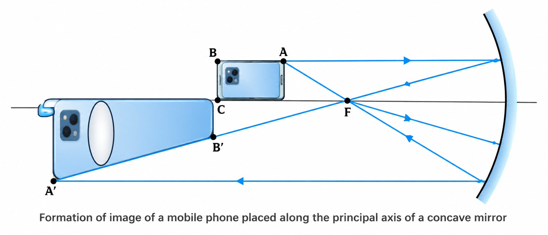
Figure 9.7: Non-uniform longitudinal magnification of an object lying along the principal axis.
2. Refraction of Light at Plane Interfaces
- Snell's Law: $\mathbf{\frac{\sin i}{\sin r} = n_{21} = \frac{n_2}{n_1} = \frac{v_1}{v_2} = \frac{\lambda_1}{\lambda_2}}$. Frequency $\nu$ remains strictly unchanged during refraction!
- Optical vs Mass Density: Turpentine oil has lower mass density than water ($870\text{ kg m}^{-3} < 1000\text{ kg m}^{-3}$) but is optically denser ($n \approx 1.47 > 1.33$).
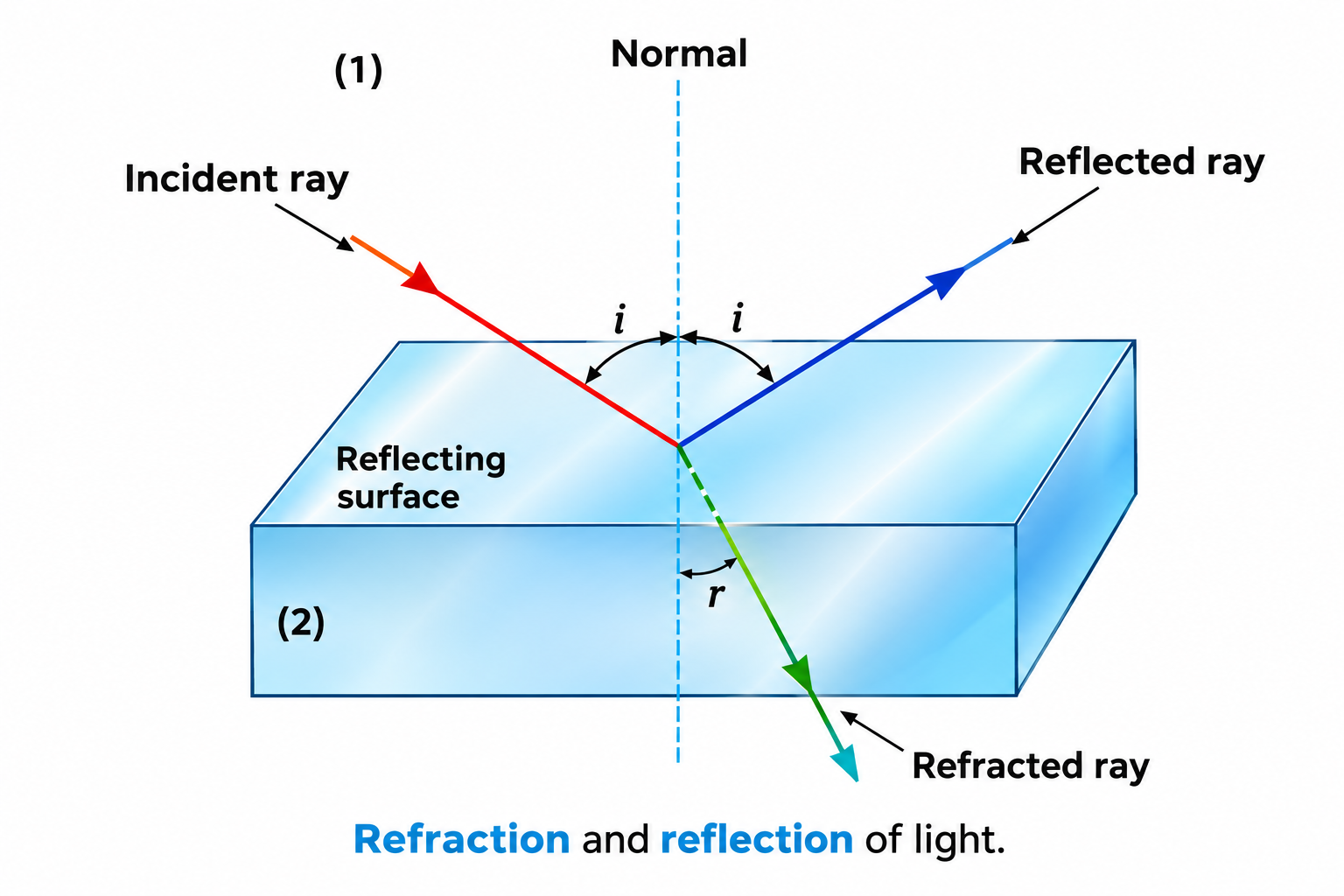
Figure 9.8: Refraction and reflection at a plane interface between two optical media.
Lateral Shift in a Glass Slab
For a rectangular slab of thickness $t$, emergent ray is strictly parallel to the incident ray ($i_1 = r_2'$).
Perpendicular lateral shift: $\mathbf{x = \frac{t \sin(i - r)}{\cos r}}$.
Shift $x$ increases with: slab thickness $t$, angle of incidence $i$, refractive index $n$, and decreasing wavelength (violet shifts more than red).
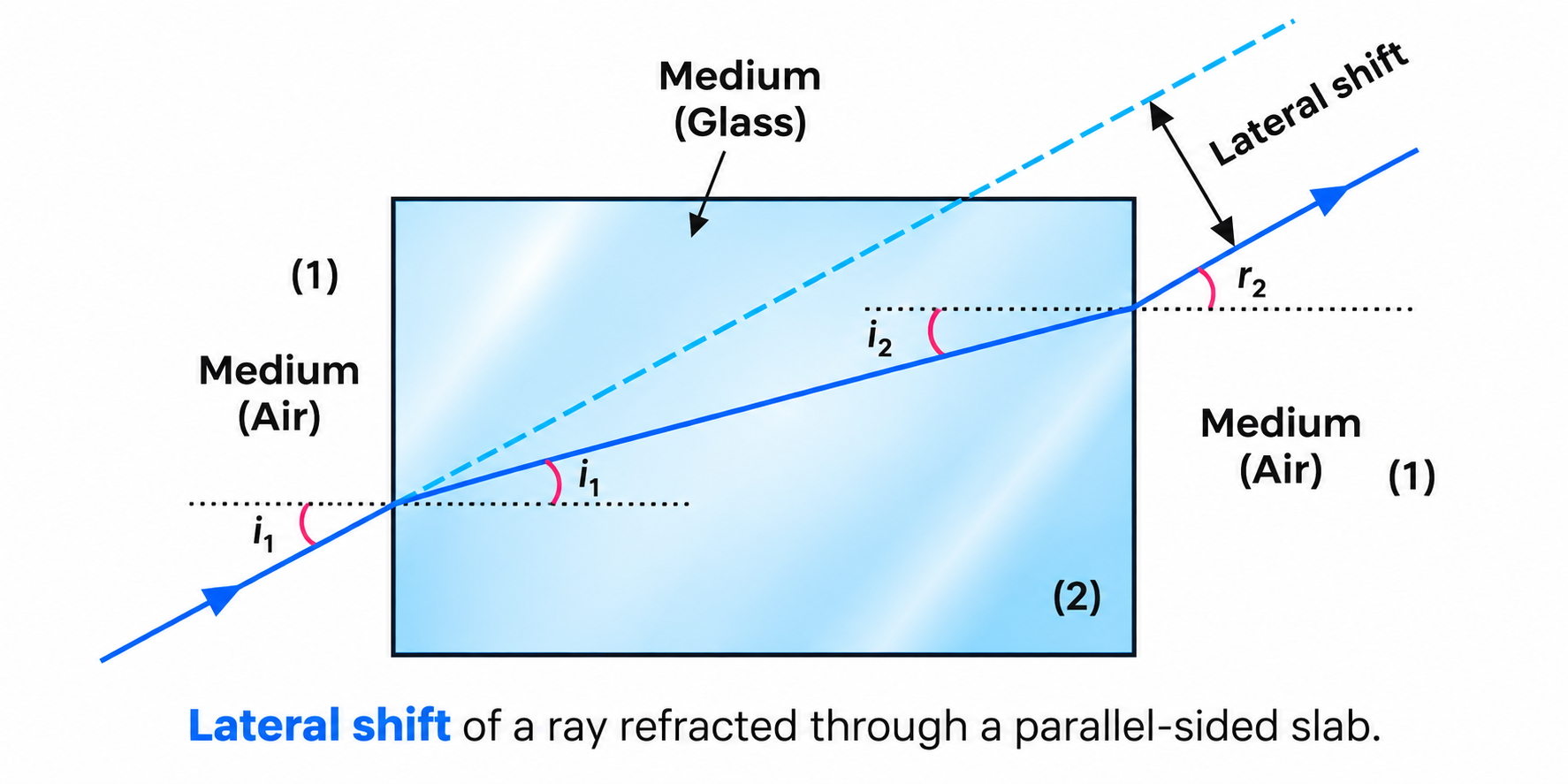
Figure 9.9: Lateral displacement of a ray passing through a parallel-sided glass slab.
Apparent Depth & Normal Shift
When viewing an object in a denser medium ($n$) from a rarer medium (air) near normal incidence:
$$\mathbf{\text{Apparent Depth } (h') = \frac{\text{Real Depth } (h)}{n}} \implies \mathbf{\text{Normal Shift } (d) = h - h' = t\left(1 - \frac{1}{n}\right)}$$
For multiple liquid layers: $\mathbf{d_{total} = \sum t_i \left(1 - \frac{1}{n_i}\right)}$.
Inverse Case (Object in air viewed from water): Apparent height is greater: $\mathbf{h' = n \cdot h}$.
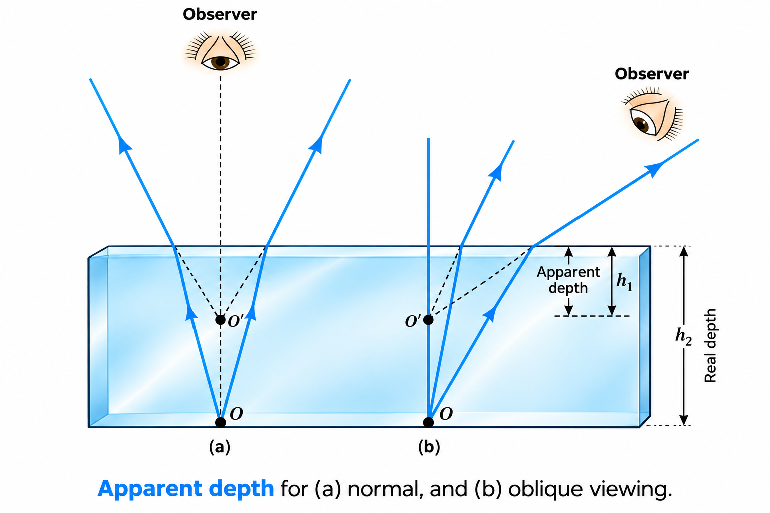
Figure 9.10: Apparent depth and normal upward shift under normal and oblique viewing.
3. Total Internal Reflection (TIR)
Mandatory Conditions for TIR
- Light must travel from an optically denser medium to an optically rarer medium.
- Angle of incidence must exceed the critical angle: $\mathbf{i > i_c}$.
Critical Angle Formula: $\mathbf{\sin i_c = \frac{n_2}{n_1}} \implies \mathbf{n = \frac{1}{\sin i_c}}$ (when rarer medium is air).
Standard Critical Angles: Water ($48.75^\circ$), Crown glass ($41.14^\circ$), Flint glass ($37.31^\circ$), Diamond ($24.41^\circ$).
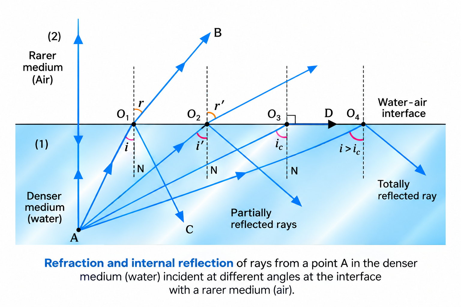
Figure 9.11: Successive rays from denser medium showing critical angle and total internal reflection.
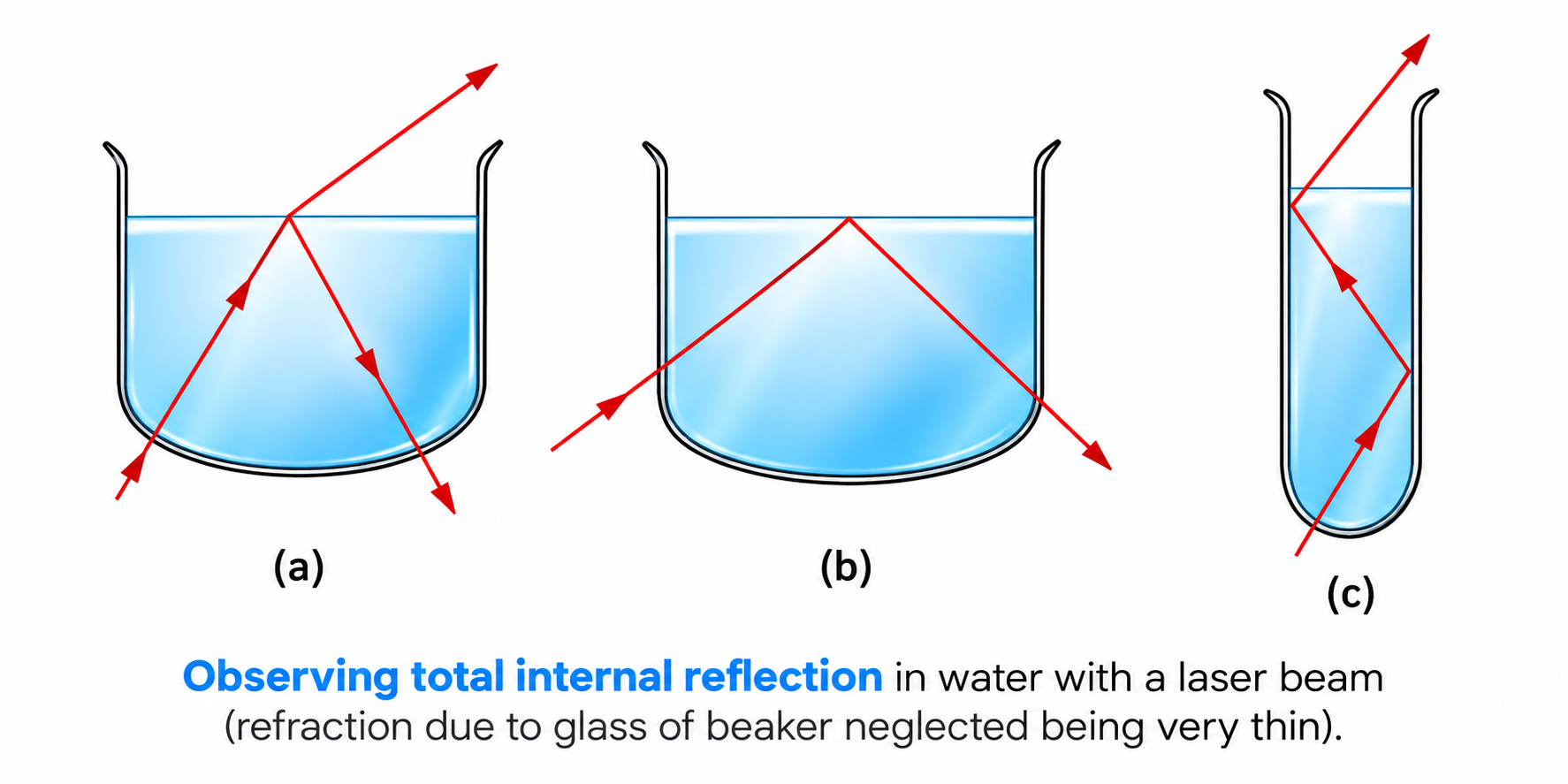
Figure 9.12: Demonstration of total internal reflection using a laser beam in water.
High-Yield Applications of TIR
- Mirage: Hot air near ground is optically rarer than upper cooler air. Downward rays bend away from normal and undergo TIR ($i > i_c$), producing an inverted virtual image resembling a water pool.
- Diamond Sparkle: Very small critical angle ($i_c \approx 24.4^\circ$) and high refractive index ($n \approx 2.42$) allow multiple internal reflections before light emerges through facets.
- Totally Reflecting Prisms ($45^\circ-90^\circ-45^\circ$): Crown glass ($i_c \approx 41.1^\circ < 45^\circ$) reflects light with 100% efficiency without silvering degradation:
- Bends rays through $90^\circ$ (periscopes) or $180^\circ$ (Porro prism in binoculars).
- Inverts images without altering size (erecting prisms).
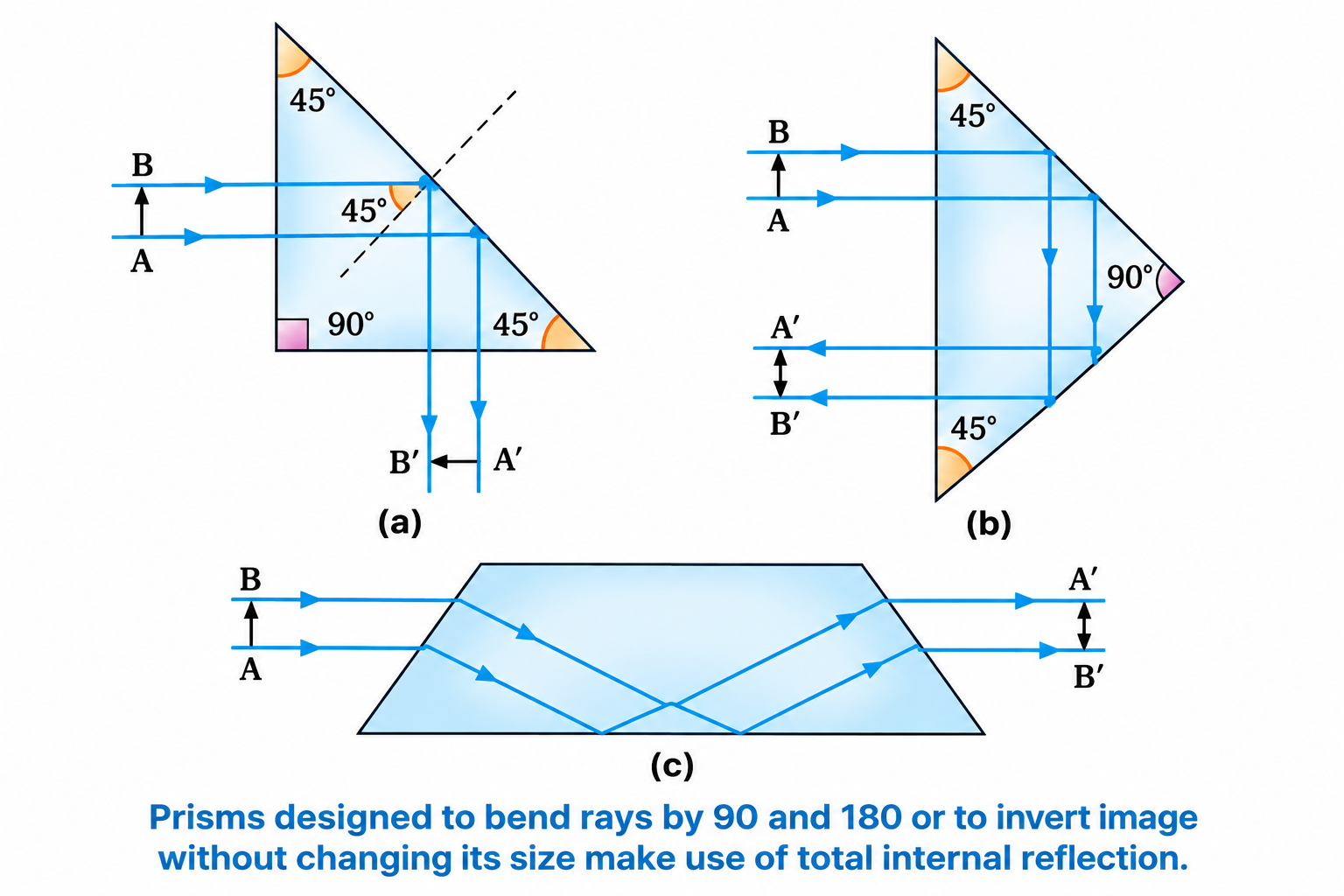
Figure 9.13: Prisms designed to bend rays by \(90^\circ\), \(180^\circ\), or invert images using TIR.
Optical Fibres & Light Pipes
Consists of a central Core ($n_1 \approx 1.68$) coated with outer Cladding ($n_2 \approx 1.44$).
Rays launched inside within the acceptance angle undergo repeated TIR with negligible loss over kilometers. Used in endoscopy, communications, and sensing.
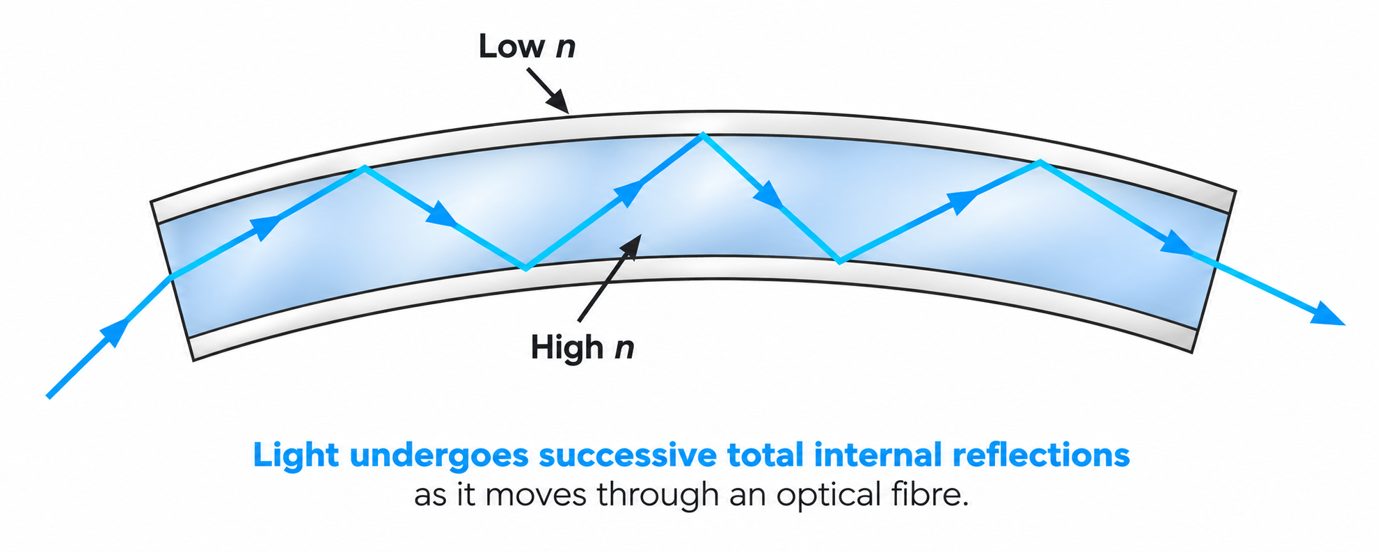
Figure 9.14: Light undergoing successive total internal reflections along the core of an optical fibre.
4. Refraction at Spherical Surfaces and Thin Lenses
Derivation Crux: Refraction at a Single Spherical Surface
Using paraxial Snell's law $n_1 i \approx n_2 r$ with exterior angles $i = \alpha + \gamma$ and $r = \gamma - \beta$ (Figure 9.15):
$$n_1\left(\frac{MN}{OM} + \frac{MN}{MC}\right) = n_2\left(\frac{MN}{MC} - \frac{MN}{MI}\right) \implies \frac{n_1}{OM} + \frac{n_2}{MI} = \frac{n_2 - n_1}{MC}$$
Applying sign convention ($OM = -u, MI = +v, MC = +R$):
$$\mathbf{\frac{n_2}{v} - \frac{n_1}{u} = \frac{n_2 - n_1}{R}}$$
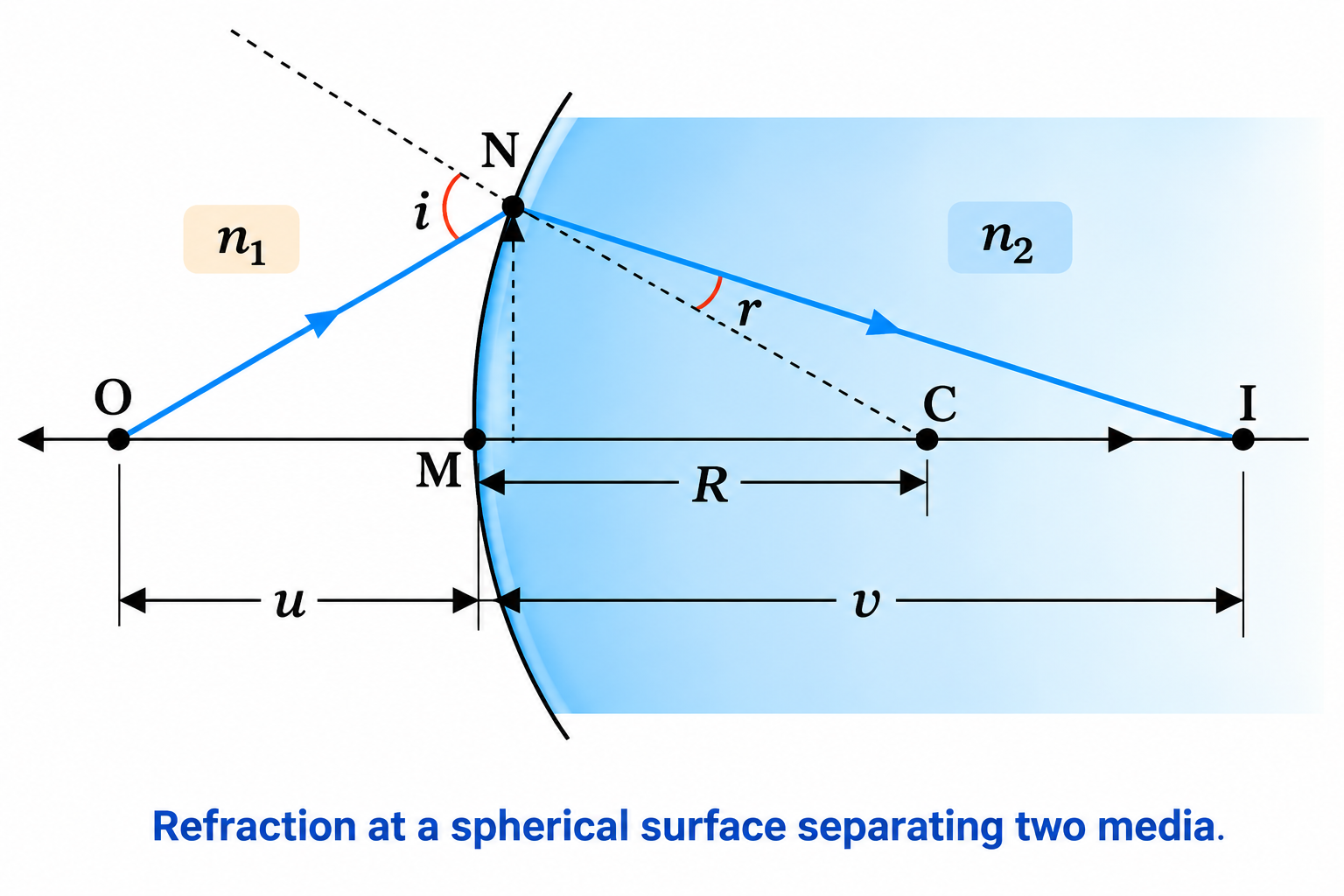
Figure 9.15: Refraction at a convex spherical surface separating medium \(n_1\) from medium \(n_2\).
Derivation Crux: Lens Maker's Formula & Thin Lens Equation
Adding interface equations for first surface $ABC$ and second surface $ADC$ (Figure 9.16):
$$\frac{n_2}{v_1} - \frac{n_1}{u} = \frac{n_2 - n_1}{R_1} \quad \text{and} \quad \frac{n_1}{v} - \frac{n_2}{v_1} = \frac{n_1 - n_2}{R_2} = -\frac{n_2 - n_1}{R_2}$$
Summing eliminates the intermediate image distance $v_1$:
$$\frac{1}{v} - \frac{1}{u} = \left(\frac{n_2}{n_1} - 1\right)\left(\frac{1}{R_1} - \frac{1}{R_2}\right)$$
When $u = \infty, v = f$, which gives the Lens Maker's Formula:
$$\mathbf{\frac{1}{f} = (n_{21} - 1)\left(\frac{1}{R_1} - \frac{1}{R_2}\right)} \quad \text{and} \quad \mathbf{\frac{1}{v} - \frac{1}{u} = \frac{1}{f}}$$
Linear Magnification for Lens: $\mathbf{m = \frac{h'}{h} = +\frac{v}{u} = \frac{f}{f + u} = \frac{f - v}{f}}$
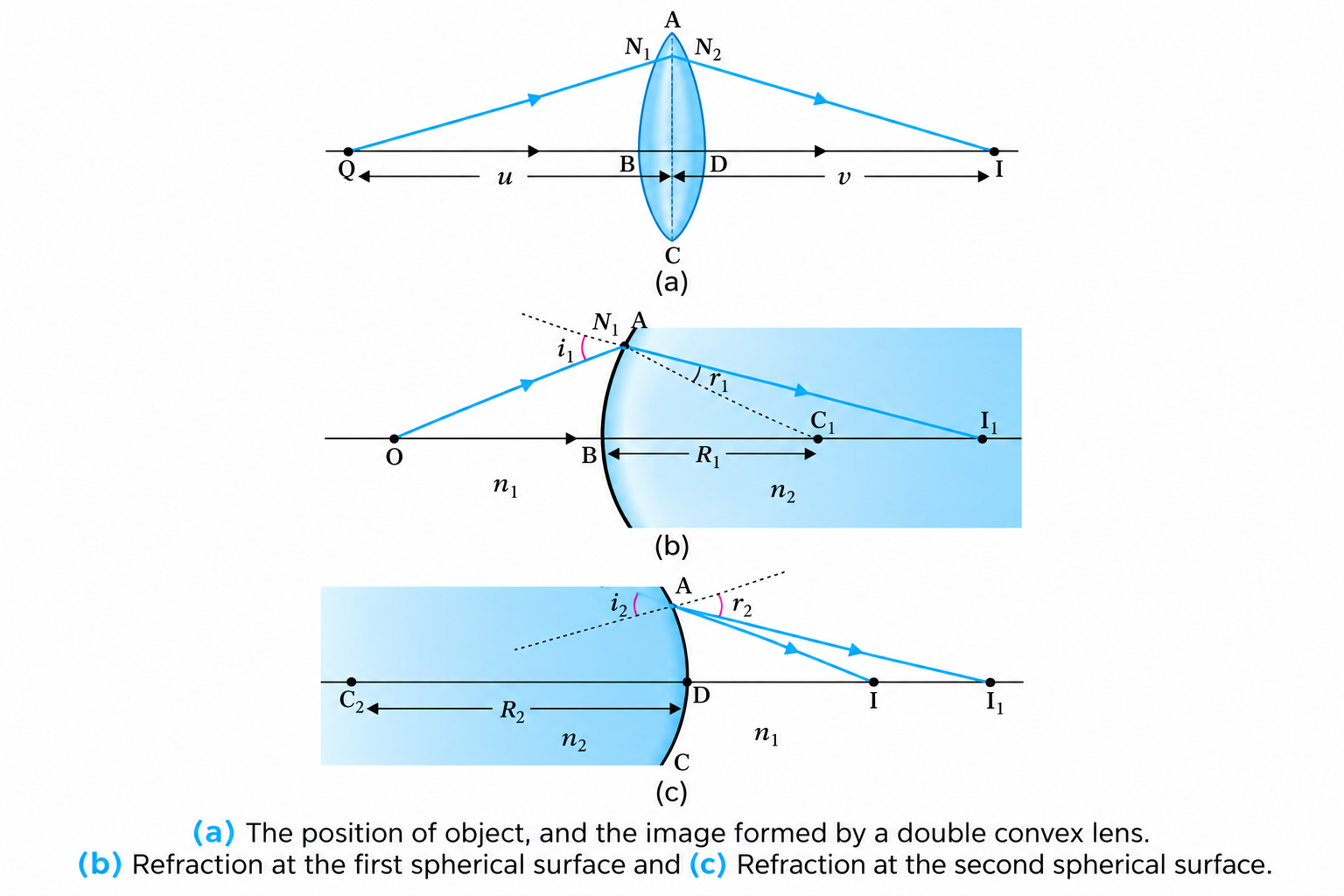
Figure 9.16: Refraction through a double convex lens showing first and second surface refractions.
Rules for Ray Tracing Through Lenses
- Ray parallel to principal axis passes through $F'$ (convex) or appears to diverge from $F$ (concave).
- Ray through optical center ($O$) passes undeviated.
- Ray through primary focus $F$ emerges parallel to principal axis.
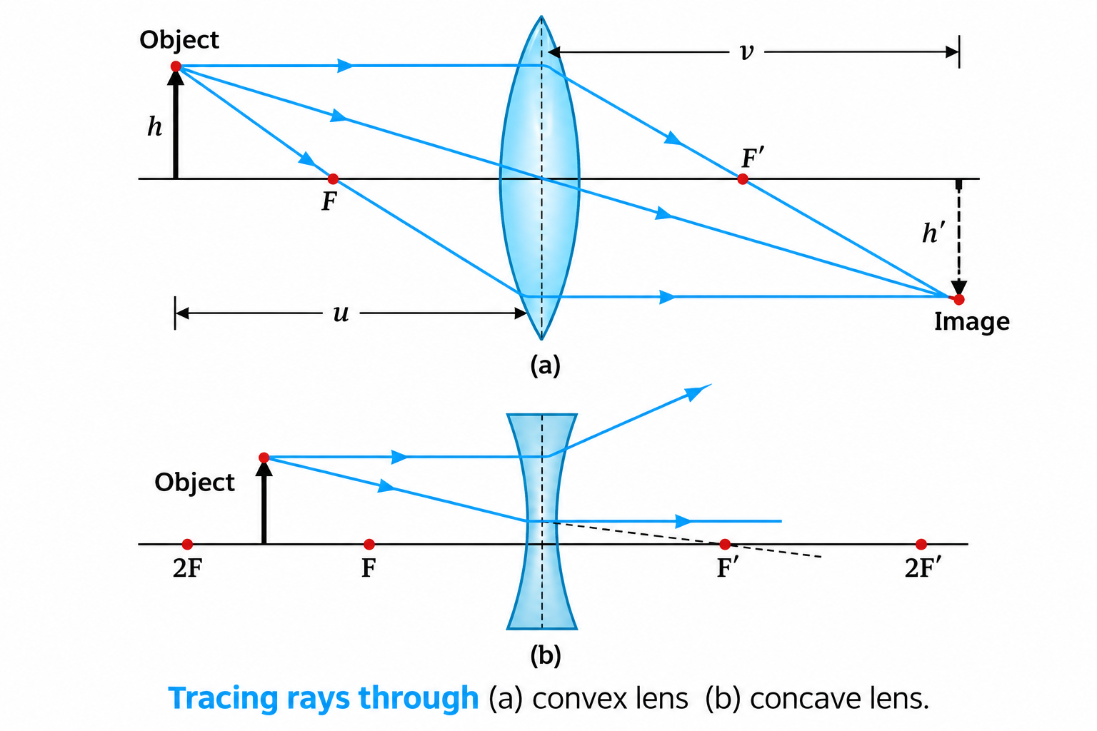
Figure 9.17: Rules for tracing rays through (a) convex lens and (b) concave lens.
Power of a Lens & Combination in Contact
Power ($P$): Converging/diverging ability of a lens: $\mathbf{P = \frac{1}{f\text{ (in meters)}}}$ in Dioptre ($\text{D}$).
Converging (convex) lens: $P > 0$; Diverging (concave) lens: $P < 0$.
Coaxial Thin Lenses in Contact:
$$\mathbf{\frac{1}{F} = \frac{1}{f_1} + \frac{1}{f_2} + \dots}, \quad \mathbf{P = P_1 + P_2 + \dots}, \quad \mathbf{m = m_1 \times m_2 \times \dots}$$
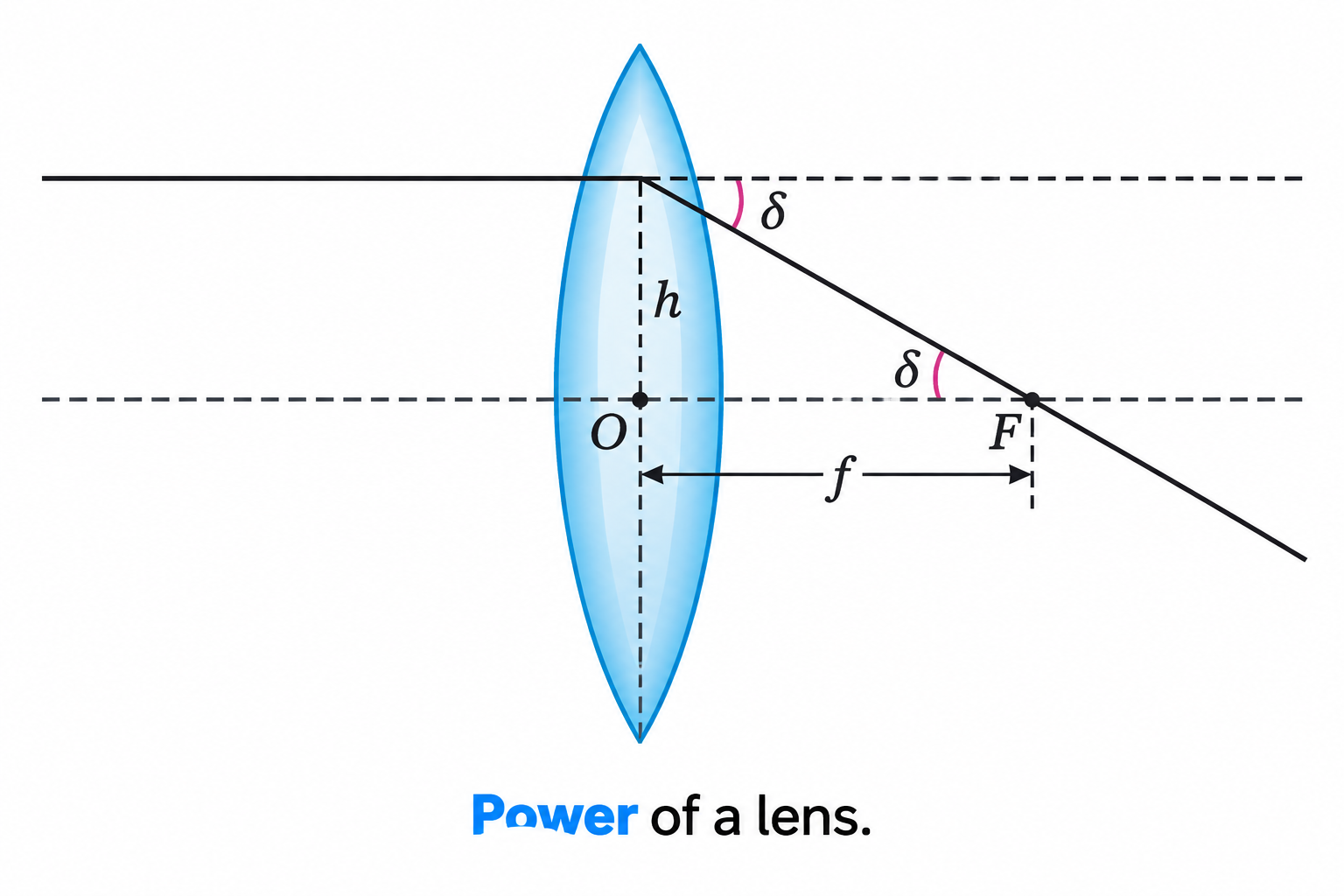
Figure 9.18: Lens power defined by deviation \(\delta\) for a ray incident at unit height \(h = 1\text{ m}\).
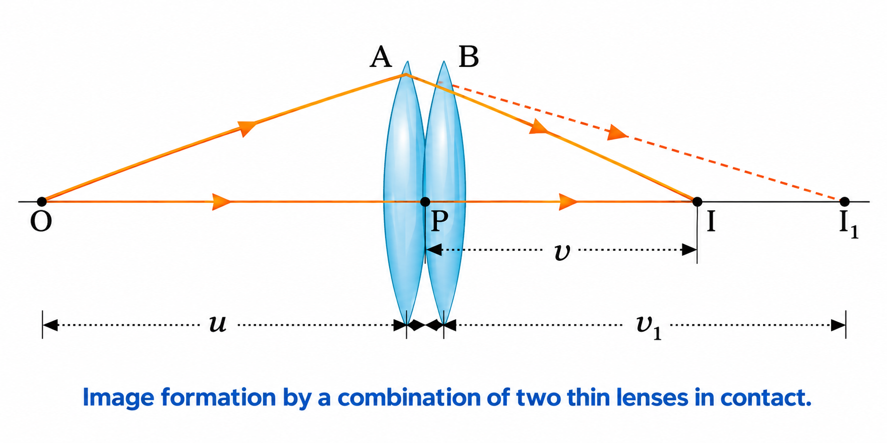
Figure 9.19: Image formation by two thin coaxial lenses in contact.
High-Yield Competitive Rules: Lens Alterations
- Lens in a liquid medium: $\frac{f_m}{f_a} = \frac{(n_g - 1)}{(n_g/n_m - 1)}$. In water ($n_m = 4/3$), $\mathbf{f_{water} = 4 f_{air}}$. If $n_m = n_g$, $f \to \infty$ (lens becomes invisible plate). If $n_m > n_g$, lens nature reverses!
- Transverse vertical cut: Cutting equiconvex lens ($f$) vertically into two halves produces plano-convex lenses with $\mathbf{f' = 2f, P' = P/2}$.
- Longitudinal horizontal cut: Cutting along principal axis keeps radii unchanged $\implies \mathbf{f' = f}$; aperture halved $\implies$ intensity halved.
5. Refraction through a Prism & Dispersion
The Prism Formula & Minimum Deviation
From quadrilateral and triangle geometry of triangular prism (Figure 9.21):
$$\mathbf{r_1 + r_2 = A} \quad \text{and} \quad \mathbf{\delta = i + e - A \iff A + \delta = i + e}$$
At Minimum Deviation ($D_m$): Ray passes symmetrically, $i = e$ and $r_1 = r_2 = r = A/2$. Refracted ray is parallel to the base.
$$\mathbf{n = \frac{\sin\left(\frac{A + D_m}{2}\right)}{\sin\left(\frac{A}{2}\right)}}$$
For thin prism ($A < 10^\circ$): $\mathbf{D_m = (n - 1)A}$.
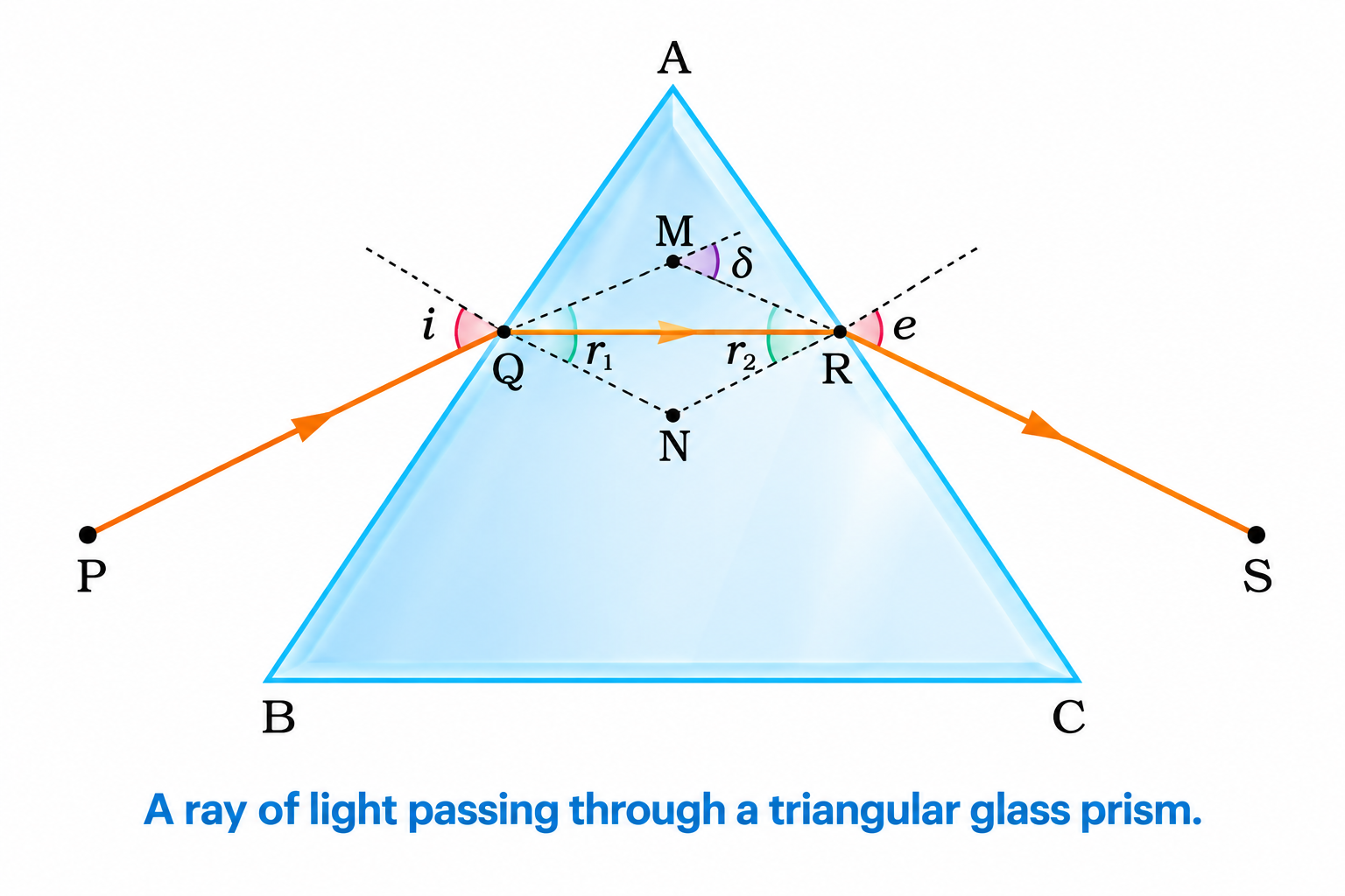
Figure 9.21: Ray path, angles of incidence, refraction, emergence, and deviation in a triangular prism.
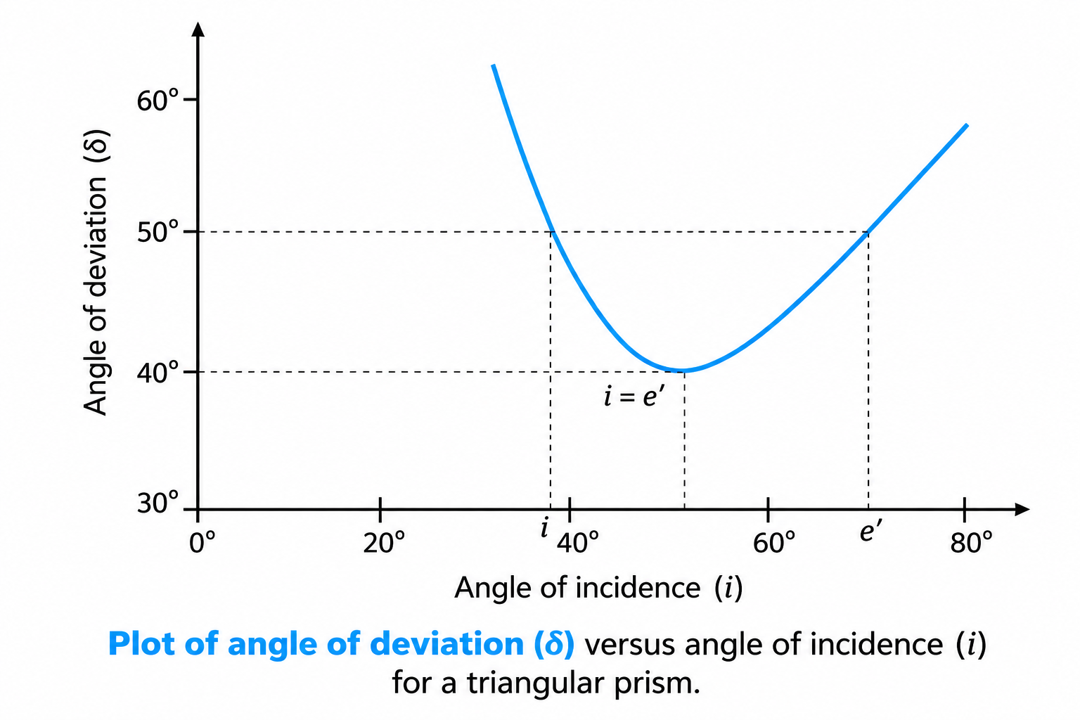
Figure 9.22: Plot of angle of deviation \(\delta\) versus angle of incidence \(i\) showing unique minimum deviation \(D_m\).
Dispersion of Light
- Cause: Cauchy's formula $n(\lambda) = A + B/\lambda^2$. Since $\lambda_r > \lambda_v \implies n_r < n_v \implies \delta_r < \delta_v$. Red light deviates the least; violet light deviates the most.
- Angular Dispersion: $\mathbf{\theta = \delta_v - \delta_r = (n_v - n_r)A}$.
- Dispersive Power: $\mathbf{\omega = \frac{\delta_v - \delta_r}{\delta_y} = \frac{n_v - n_r}{n_y - 1}}$.
- Rainbow:
- Primary Rainbow: 2 refractions + 1 internal reflection. Red on outer ring ($42^\circ$), violet on inner ($40^\circ$).
- Secondary Rainbow: 2 refractions + 2 internal reflections. Fainter, reversed color order (violet outer $53^\circ$, red inner $50^\circ$).
6. Scattering of Light
Rayleigh's Law of Scattering
For scattering particles smaller than wavelength ($a \ll \lambda$):
$$\mathbf{I \propto \frac{1}{\lambda^4}}$$
Scattering intensity is inversely proportional to the 4th power of wavelength.
- Blue Color of Clear Sky: Blue light has shorter wavelength ($\sim 1.8\times$ shorter than red) and scatters $\sim (1.8)^4 \approx 10\text{–}15$ times more strongly.
- Reddish Sunrise and Sunset: Sunlight traverses maximum atmospheric path; blue is scattered out, leaving longer wavelengths (red/orange) to reach the eye directly.
- Danger Signals are Red: Red light scatters least and penetrates smoke/fog over maximum distances.
- White Clouds: Droplets have size $a \gg \lambda \implies$ Rayleigh's law fails; all wavelengths are scattered equally (Mie scattering), appearing white.
7. Optical Instruments: Formulas & Ray Diagrams
7.1 The Simple Microscope (Magnifier)
A single convex lens of short focal length $f$. Object placed between $O$ and $F$ forms an erect, magnified, virtual image.
Simple Microscope Formulas
$$\text{Angular Magnification } m = \frac{\beta}{\alpha}$$
- Case 1: Image at Near Point ($v = -D = -25\text{ cm}$ • Maximum Strain):
$$\mathbf{m = 1 + \frac{D}{f}}$$
- Case 2: Normal Adjustment (Image at Infinity • Relaxed Eye):
$$\mathbf{m = \frac{D}{f}}$$
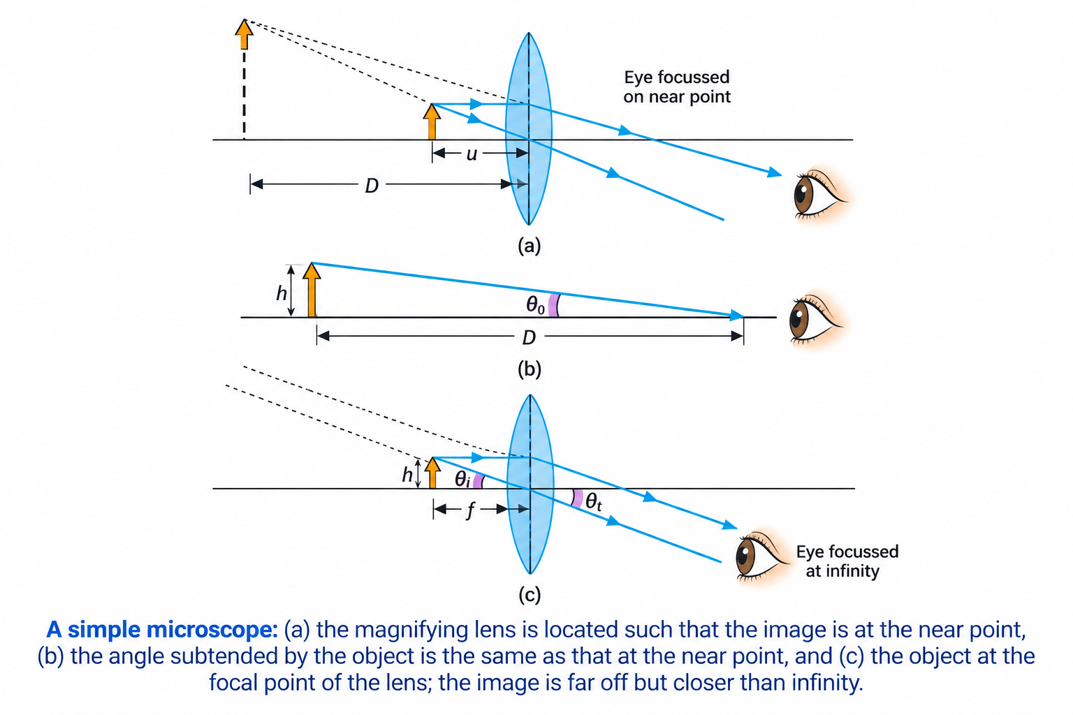
Figure 9.23: Simple microscope: (a) image at near point \(D\), (b) unaided eye, and (c) normal adjustment (image at infinity).
7.2 The Compound Microscope
Uses two convex lenses: Objective ($O$) with very short $f_o$ and small aperture; Eyepiece ($E$) with short $f_e$ ($f_e > f_o$) and larger aperture.
Compound Microscope Formulas
Total Magnification: $\mathbf{m = m_o \times m_e \approx -\left(\frac{L}{f_o}\right) m_e}$
- Case 1: Image at Near Point ($D = 25\text{ cm}$):
$$\mathbf{m = -\left(\frac{L}{f_o}\right)\left(1 + \frac{D}{f_e}\right) \approx -\left(\frac{v_o}{u_o}\right)\left(1 + \frac{D}{f_e}\right)}, \quad \mathbf{L_{tube} = v_o + u_e}$$
- Case 2: Normal Adjustment (Image at Infinity • Relaxed Eye):
$$\mathbf{m = -\left(\frac{L}{f_o}\right)\left(\frac{D}{f_e}\right) \approx -\left(\frac{v_o}{u_o}\right)\left(\frac{D}{f_e}\right)}, \quad \mathbf{L_{tube} = v_o + f_e}$$
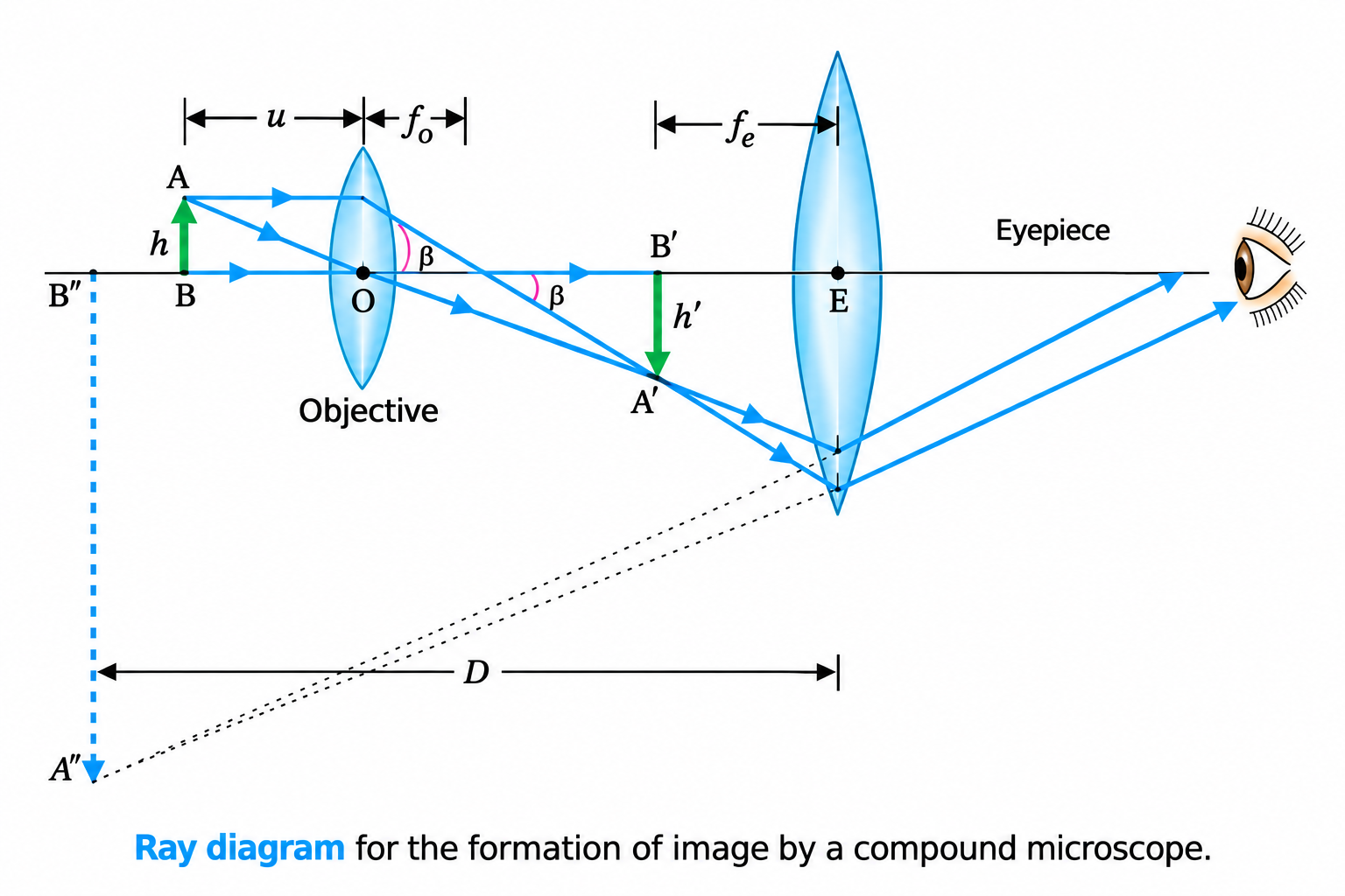
Figure 9.24: Complete ray diagram of image formation in a compound microscope.
7.3 Astronomical Telescope (Refracting Type)
Observes distant objects. Objective ($O$) has large focal length $f_o$ and very large aperture (to maximize light gathering & resolution). Eyepiece ($E$) has small focal length $f_e$.
Astronomical Refracting Telescope Formulas
$$\text{Magnifying Power } m = \frac{\beta}{\alpha}$$
- Case 1: Normal Adjustment (Image at Infinity • Relaxed Eye):
$$\mathbf{m = \frac{f_o}{f_e}}, \quad \text{Tube Length } \mathbf{L = f_o + f_e}$$
- Case 2: Image at Near Point ($D = 25\text{ cm}$):
$$\mathbf{m = \frac{f_o}{f_e}\left(1 + \frac{f_e}{D}\right)}, \quad \text{Tube Length } \mathbf{L = f_o + u_e}$$
7.4 Reflecting Telescopes (Cassegrain Telescope)
Uses a large concave paraboloidal primary mirror and a convex secondary mirror to focus light through a central hole in the primary.
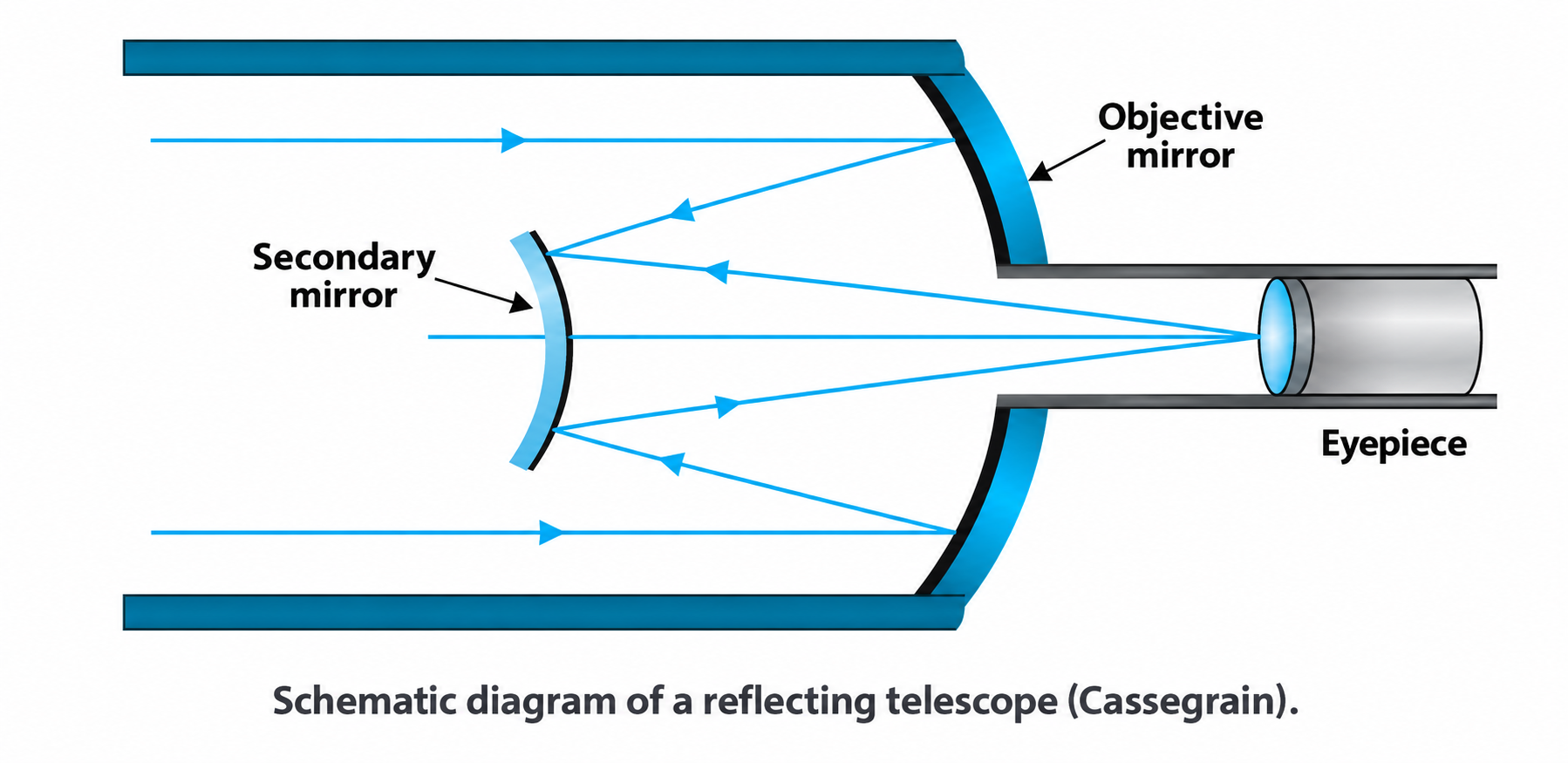
Figure 9.26: Schematic diagram of a Cassegrain reflecting telescope using a primary concave mirror and secondary convex mirror.
4 Major Advantages of Reflecting over Refracting Telescopes (CBSE Favorite)
- Zero Chromatic Aberration: Reflection does not depend on wavelength; mirrors reflect all colors identically.
- Zero Spherical Aberration: A paraboloidal primary mirror focuses all parallel rays to a single geometric point.
- Mechanical Support: Heavy mirrors can be supported across their entire back surface, preventing gravitational sagging.
- Cost & Practicality: Only one front optical surface needs grinding and polishing, enabling giant apertures (e.g., Keck $10\text{ m}$).
8. Master Formula Cheat Sheet (Quick Recall)
| Optical Element / Phenomenon |
Master Formula |
Key Conventions & Notes |
| Mirror Formula & Magnification |
$\frac{1}{v} + \frac{1}{u} = \frac{1}{f}, \quad m = -\frac{v}{u}$ |
$f = R/2$. Concave $f < 0$, Convex $f > 0$. Real object $u < 0$. |
| Refraction & Snell's Law |
$n_{21} = \frac{\sin i}{\sin r} = \frac{n_2}{n_1} = \frac{v_1}{v_2}$ |
Frequency $\nu$ constant; $\lambda = v/\nu$. |
| Normal Shift & Lateral Shift |
$d = t\left(1 - \frac{1}{n}\right), \quad x = \frac{t\sin(i-r)}{\cos r}$ |
Apparent depth $h' = h/n$ for normal viewing. |
| Critical Angle & TIR |
$\sin i_c = \frac{n_2}{n_1} = \frac{1}{n}$ |
Denser $\to$ rarer medium; $i > i_c$. |
| Single Spherical Surface |
$\frac{n_2}{v} - \frac{n_1}{u} = \frac{n_2 - n_1}{R}$ |
Light travels from medium $n_1$ into medium $n_2$. |
| Lens Maker's & Thin Lens |
$\frac{1}{f} = (n_{21}-1)\left(\frac{1}{R_1} - \frac{1}{R_2}\right) = \frac{1}{v} - \frac{1}{u}$ |
$m = +v/u$. Equiconvex in air: $f = R/[2(n-1)]$. |
| Power & Contact Combination |
$P = \frac{1}{f\text{ (m)}}, \quad P = \sum P_i, \quad \frac{1}{F} = \sum \frac{1}{f_i}$ |
Unit: Dioptre ($\text{D}$). Convex $P > 0$, Concave $P < 0$. |
| Prism Formula |
$n = \frac{\sin\left(\frac{A + D_m}{2}\right)}{\sin(A/2)}, \quad D_m = (n-1)A$ |
At min deviation: $r = A/2, i = (A + D_m)/2$. Ray $\parallel$ base. |
| Simple Microscope |
$m = 1 + \frac{D}{f}$ (near pt), $\quad m = \frac{D}{f}$ ($\infty$) |
$D = 25\text{ cm}$. Convex lens of short $f$. |
| Compound Microscope |
$m \approx -\left(\frac{L}{f_o}\right)\left(1 + \frac{D}{f_e}\right), \quad m_\infty \approx -\left(\frac{L}{f_o}\right)\left(\frac{D}{f_e}\right)$ |
$L_{tube} = v_o + u_e$ (near pt); $L_{tube} = v_o + f_e$ ($\infty$). $f_o < f_e$. |
| Astronomical Telescope |
$m_\infty = \frac{f_o}{f_e}, \quad L = f_o + f_e$ |
Near point: $m = \frac{f_o}{f_e}\left(1 + \frac{f_e}{D}\right), \quad L = f_o + u_e$. $f_o \gg f_e$. |