Vardaan Learning Institute
Class 12 Physics • Comprehensive Chapter Notes
🌐 vardaanlearning.com📞 9508841336
Chapter 9: Ray Optics and Optical Instruments
Dear Class 12 Aspirant! Ray Optics (Geometrical Optics) forms one of the most conceptually rich and heavily weighted sections of the CBSE Class 12 Physics syllabus as well as competitive examinations like JEE and NEET. This module meticulously covers the complete NCERT theory, step-by-step derivations, ray diagrams, sign conventions, optical instruments, and core problem-solving methodologies.
1. Introduction: Nature and Propagation of Light
Light is electromagnetic radiation belonging to the visible spectrum, corresponding to wavelengths roughly in the range of $400\text{ nm}$ to $750\text{ nm}$ ($4000\text{ \AA} - 7500\text{ \AA}$).
- Speed of Light: Light travels with the maximum attainable speed in vacuum, precisely given by:
$$\mathbf{c = 2.99792458 \times 10^8\text{ m s}^{-1} \approx 3 \times 10^8\text{ m s}^{-1}}$$
- Rectilinear Propagation: In a homogeneous medium, light travels in straight lines. Although light is fundamentally a wave, because its wavelength ($\sim 10^{-7}\text{ m}$) is incomparably smaller than the macroscopic dimensions of ordinary optical elements (mirrors, lenses, apertures of size several centimeters), diffraction and wave bending effects are negligible in macroscopic setups. Thus, light can be treated as travelling along straight geometric paths called rays of light.
- Ray and Beam: A straight line indicating the direction of propagation of light energy is called a ray. A collection or bundle of such rays constitutes a beam of light.
2. Reflection of Light by Spherical Mirrors
When light travelling in a medium strikes a polished boundary surface and returns into the same medium, the phenomenon is called reflection.
2.1 Fundamental Laws of Reflection
- The angle of incidence ($\angle i$) is strictly equal to the angle of reflection ($\angle r'$):
$$\mathbf{\angle i = \angle r'}$$
- The incident ray, the reflected ray, and the normal to the reflecting surface at the point of incidence all lie in the same plane.
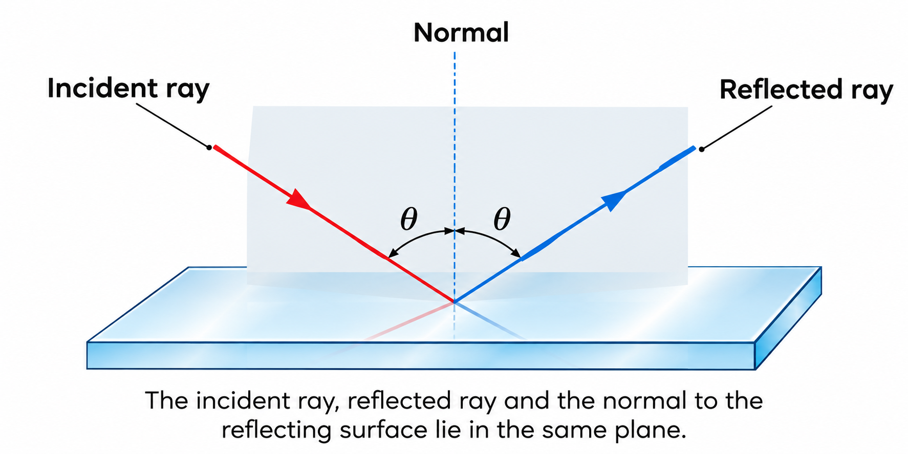
Figure 9.1: The incident ray, reflected ray and the normal to the reflecting surface lie in the same plane.
Crucial Note: These laws hold true at every single point of any reflecting surface, whether planar or curved. For curved surfaces, the normal at any point is along the radius connecting the center of curvature $C$ to that point.
2.2 Key Terminology for Spherical Mirrors
A spherical mirror is a curved reflecting surface that forms part of a hollow sphere of glass:
- Concave Mirror: The outer bulged surface is silvered; reflection occurs from the inner concave surface (converging mirror).
- Convex Mirror: The inner hollow surface is silvered; reflection occurs from the outer bulged surface (diverging mirror).
- Pole ($P$): The geometric center of the reflecting spherical surface.
- Center of Curvature ($C$): The center of the hollow sphere of which the mirror forms a part. The normal at any point on the mirror passes through $C$.
- Radius of Curvature ($R$): The radius of the sphere of which the mirror forms a part ($PC = R$).
- Principal Axis: The straight line passing through the Pole ($P$) and the Center of Curvature ($C$).
- Aperture: The effective diameter of the reflecting surface of the mirror.
- Paraxial Rays: Rays that strike the mirror very close to the pole $P$ and make extremely small angles with the principal axis ($\sin \theta \approx \tan \theta \approx \theta$). Throughout geometric optics derivations, we assume paraxial rays.
2.3 The Cartesian Sign Convention (MANDATORY for Numericals)
To establish unified mathematical relationships valid for all mirror and lens configurations, the Cartesian Sign Convention is strictly followed:
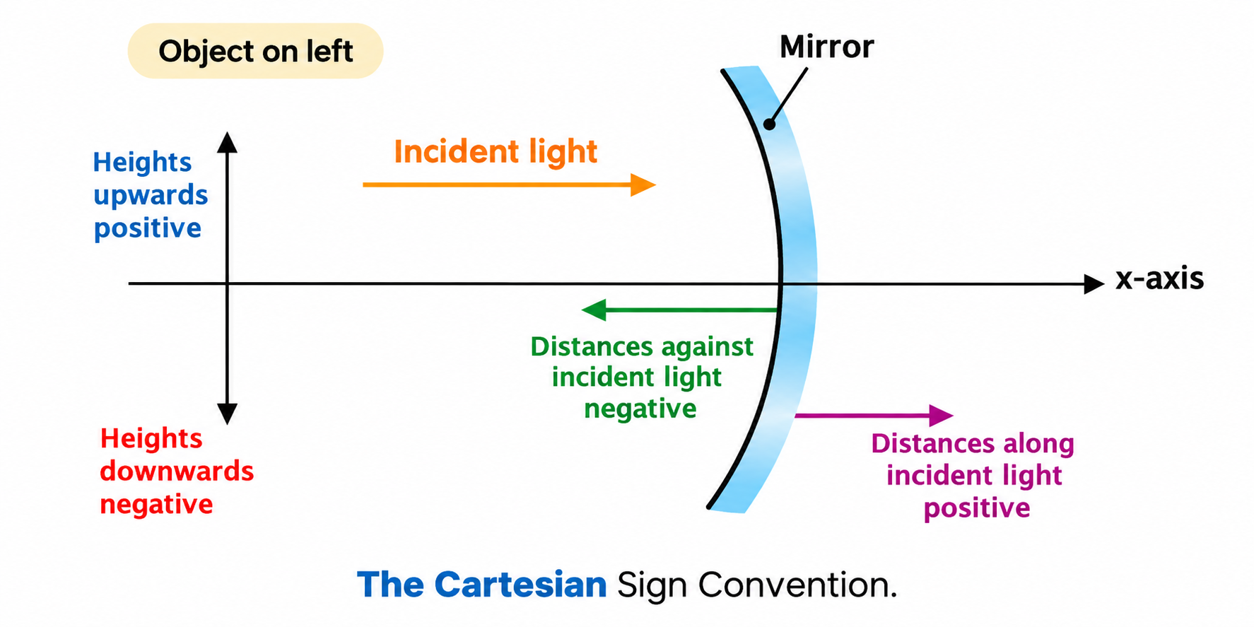
Figure 9.2: The Cartesian Sign Convention for measuring distances in spherical mirrors and lenses.
- The Pole ($P$) of the mirror (or Optical Centre of a lens) is taken as the origin $(0,0)$, and the principal axis is taken as the $x$-axis.
- Light is always considered to be incident from the left to the right.
- All distances measured along the principal axis in the direction of incident light (to the right of $P$) are taken as positive (+ve).
- All distances measured opposite to the direction of incident light (to the left of $P$) are taken as negative (-ve). Therefore, for a real object placed in front of a mirror, object distance $u$ is ALWAYS negative.
- Heights measured upward and perpendicular to the principal axis ($+y$ direction) are positive (+ve).
- Heights measured downward and perpendicular to the principal axis ($-y$ direction) are negative (-ve).
2.4 Principal Focus ($F$) and Focal Length ($f$)
- Concave Mirror: A parallel beam of paraxial rays after reflection actually converges at a point $F$ on the principal axis. Hence, a concave mirror has a real focus located in front of it ($f < 0$).
- Convex Mirror: A parallel beam of paraxial rays after reflection appears to diverge from a point $F$ behind the mirror. Hence, a convex mirror has a virtual focus ($f > 0$).
- Focal Plane: A plane passing through the principal focus $F$ and perpendicular to the principal axis. An oblique parallel beam of rays converges to a point in the focal plane.
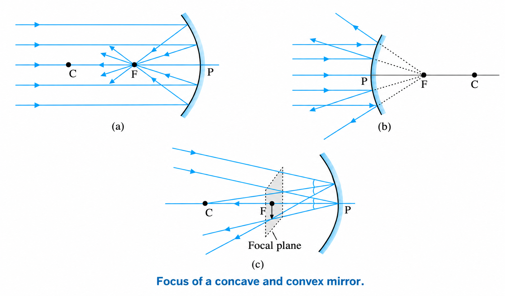
Figure 9.3: Focus of (a) a concave mirror, (b) a convex mirror, and (c) the focal plane.
Derivation: Focal Length & Radius of Curvature ($f = R/2$)
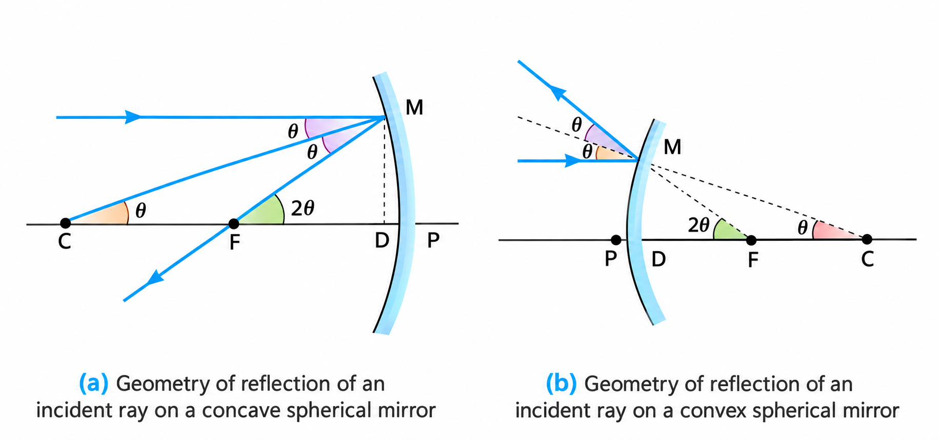
Figure 9.4: Geometry of reflection of an incident ray on (a) concave spherical mirror, and (b) convex spherical mirror for deriving \(f = R/2\).
Consider a ray parallel to the principal axis striking a concave mirror at point $M$. The radius $CM$ is normal to the mirror at $M$.
Let $\theta$ be the angle of incidence. By the law of reflection, $\angle CMF = \theta$.
Since the incident ray is parallel to the principal axis, the alternate angle $\angle MCP = \theta$.
Also, the exterior angle $\angle MFP = \angle MCP + \angle CMF = \theta + \theta = 2\theta$.
Draw perpendicular $MD$ from $M$ onto the principal axis. In right-angled triangles $\triangle MDC$ and $\triangle MDF$:
$$\tan \theta = \frac{MD}{CD} \quad \text{and} \quad \tan 2\theta = \frac{MD}{FD}$$
For paraxial rays, $\theta$ is very small, so $\tan \theta \approx \theta$ and $\tan 2\theta \approx 2\theta$. Thus:
$$\frac{MD}{FD} = 2 \left(\frac{MD}{CD}\right) \implies FD = \frac{CD}{2}$$
For mirrors of small aperture, the point $D$ lies extremely close to the pole $P$, so $FD \approx FP = f$ and $CD \approx CP = R$.
$$\mathbf{f = \frac{R}{2}}$$
Conclusion: The principal focus of a spherical mirror lies midway between the pole and the center of curvature.
2.5 Rules for Ray Tracing (Image Formation)
To locate the image formed by a spherical mirror, we trace the intersection of any two of the following four standard rays:
- Ray parallel to the principal axis: Passes through the focus $F$ after reflection (concave mirror) or appears to diverge from $F$ (convex mirror).
- Ray passing through the center of curvature $C$: Hits the surface normally ($\angle i = 0$) and retraces its path back along the same line.
- Ray passing through the focus $F$: Emerges parallel to the principal axis after reflection.
- Ray incident at the pole $P$: Is reflected symmetrically about the principal axis such that $\angle i = \angle r$.
5-Mark Derivation: The Mirror Equation & Magnification
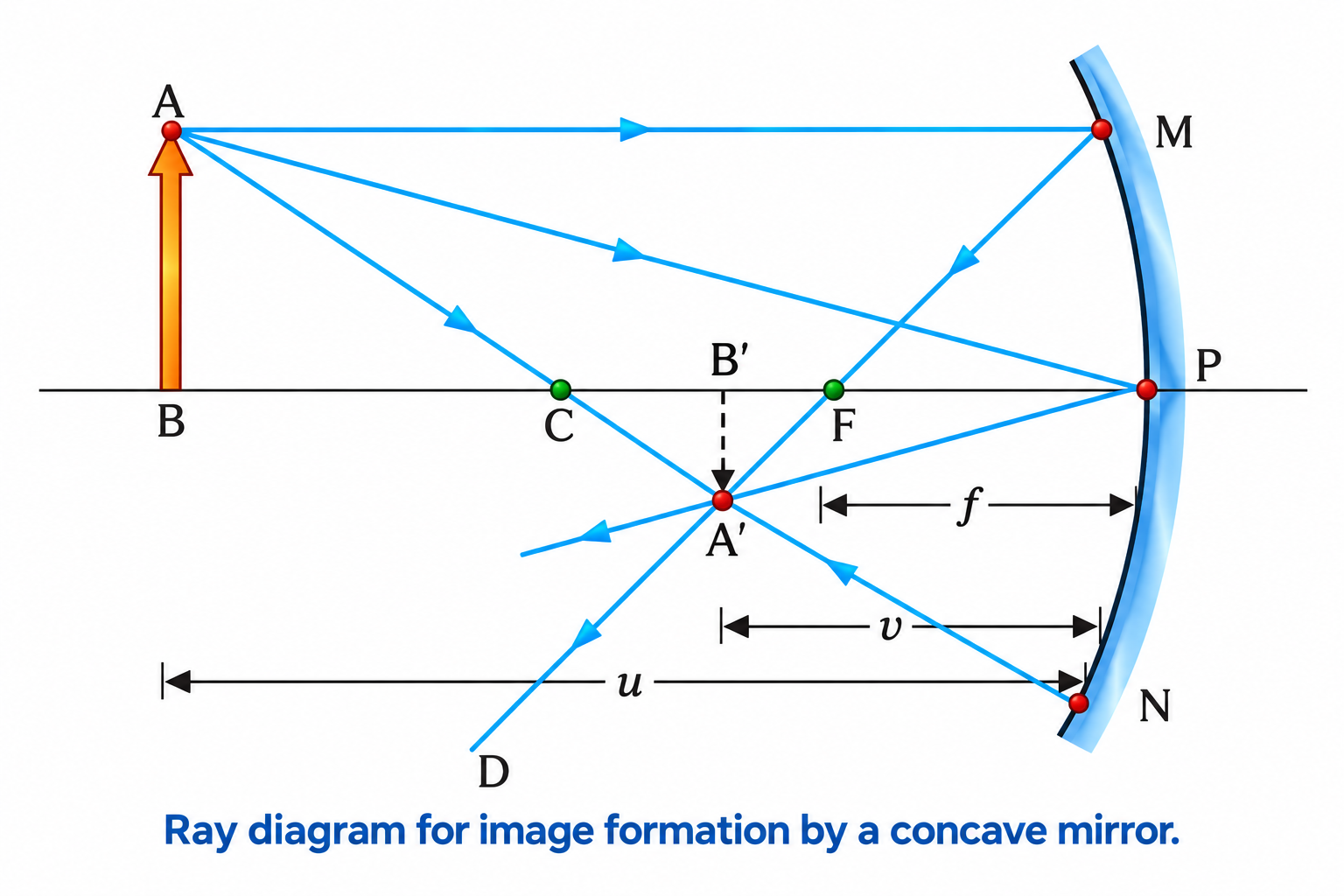
Figure 9.5: Ray diagram for image formation by a concave mirror (Derivation of the Mirror Equation).
Derivation of the Mirror Equation:
In Figure 9.5, an object $AB$ of height $h$ is placed perpendicular to the principal axis beyond $C$ of a concave mirror. A real, inverted image $A'B'$ of height $h'$ is formed between $C$ and $F$.
1. Right-angled triangles $\triangle A'B'F$ and $\triangle MPF$ are similar (for small aperture, $MP$ is perpendicular to $CP$):
$$\frac{B'A'}{PM} = \frac{B'F}{FP} \implies \frac{B'A'}{BA} = \frac{B'F}{FP} \quad (\because PM = BA) \quad \text{--- (Eq. 1)}$$
2. Right-angled triangles $\triangle A'B'P$ and $\triangle ABP$ are also similar (since $\angle APB = \angle A'PB'$):
$$\frac{B'A'}{BA} = \frac{B'P}{BP} \quad \text{--- (Eq. 2)}$$
3. Equating (Eq. 1) and (Eq. 2):
$$\frac{B'F}{FP} = \frac{B'P}{BP} \implies \frac{B'P - FP}{FP} = \frac{B'P}{BP} \quad \text{--- (Eq. 3)}$$
4. Applying the Cartesian Sign Convention:
$$B'P = -v, \quad FP = -f, \quad BP = -u$$
Substituting these into (Eq. 3):
$$\frac{-v - (-f)}{-f} = \frac{-v}{-u} \implies \frac{-v + f}{-f} = \frac{v}{u} \implies \frac{v - f}{f} = \frac{v}{u}$$
$$\frac{v}{f} - 1 = \frac{v}{u} \implies \frac{v}{f} = 1 + \frac{v}{u}$$
Dividing the entire equation by $v$:
$$\mathbf{\frac{1}{v} + \frac{1}{u} = \frac{1}{f}}$$
Linear Magnification ($m$):
From $\triangle A'B'P \sim \triangle ABP$: $\frac{B'A'}{BA} = \frac{B'P}{BP}$.
Applying signs: $B'A' = -h'$, $BA = +h$, $B'P = -v$, $BP = -u$:
$$\frac{-h'}{h} = \frac{-v}{-u} = \frac{v}{u} \implies \mathbf{m = \frac{h'}{h} = -\frac{v}{u}}$$
Expressing magnification in terms of $f, u, v$:
$$\mathbf{m = \frac{f}{f - u} = \frac{f - v}{f}}$$
2.6 Virtual Image Formation in Spherical Mirrors
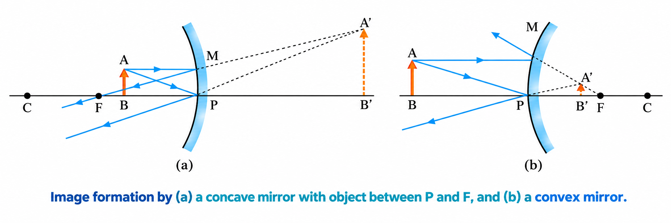
Figure 9.6: Image formation by (a) a concave mirror with object between P and F (virtual, erect, magnified), and (b) a convex mirror (virtual, erect, diminished).
Summary of Image Formation by Spherical Mirrors
| Type of Mirror |
Object Position |
Image Position |
Nature of Image |
Size of Image |
Magnification ($m$) |
Concave Mirror
($f < 0$) |
At Infinity ($\infty$) |
At Focus ($F$) |
Real & Inverted |
Highly Diminished (Point) |
$m \ll -1$ ($m \to 0^-$) |
| Beyond $C$ |
Between $C$ and $F$ |
Real & Inverted |
Diminished |
$-1 < m < 0$ |
| At $C$ |
At $C$ |
Real & Inverted |
Same size |
$m = -1$ |
| Between $C$ and $F$ |
Beyond $C$ |
Real & Inverted |
Magnified (Enlarged) |
$m < -1$ |
| At Focus ($F$) |
At Infinity ($\infty$) |
Real & Inverted |
Extremely Magnified |
$m \to -\infty$ |
| Between $P$ and $F$ |
Behind the Mirror |
Virtual & Erect |
Magnified (Enlarged) |
$m > +1$ |
Convex Mirror
($f > 0$) |
At Infinity ($\infty$) |
At Focus ($F$) behind mirror |
Virtual & Erect |
Highly Diminished |
$m \to 0^+$ |
| Between $\infty$ and Pole $P$ |
Between $P$ and $F$ behind mirror |
Virtual & Erect |
Diminished |
$0 < m < +1$ |
NCERT Conceptual Insights: Covered Mirror & Longitudinal Object
1. Effect of Covering Half of a Mirror (NCERT Example 9.1):
If the lower half of a concave mirror's reflecting surface is covered with an opaque cloth or black paper, does the mirror produce only half of the image?
Answer: NO! The full image of the complete object is still produced because every small part of the mirror obeys the laws of reflection and forms an image of the entire object. However, because the total reflecting surface area is halved, the total amount of light energy collected is reduced, so the
brightness/intensity of the image is reduced to half.
2. Distortion of Longitudinal Object / Mobile Phone (NCERT Example 9.2):
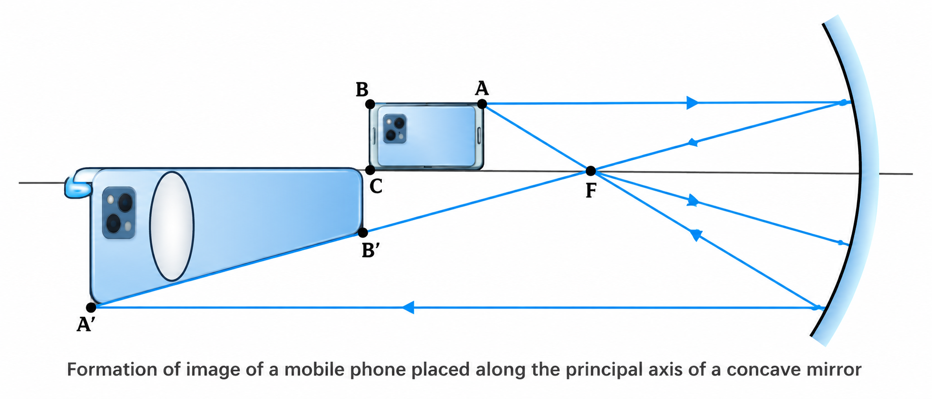
Figure 9.7: Image formation of a mobile phone lying along the principal axis of a concave mirror showing non-uniform longitudinal magnification.
When an object lies lengthwise along the principal axis (Figure 9.7), different points of the object have different object distances ($u$). Since magnification $m = -v/u$ varies continuously along the length of the object, the image suffers
non-uniform longitudinal magnification:
$$m_L = \frac{dv}{du} = -\frac{v^2}{u^2} = -m^2$$
The closer end of the phone experiences greater magnification than the farther end, producing a distorted trapezoidal image.
NCERT Example 9.4 • Velocity of Image in Convex Mirror
Problem: Suppose while sitting in a parked car, you notice a jogger approaching towards you in the side-view mirror of radius of curvature $R = 2\text{ m}$. If the jogger is running at a constant speed of $5\text{ m s}^{-1}$, how fast does the image of the jogger appear to move when the jogger is: (a) $39\text{ m}$, (b) $29\text{ m}$, (c) $19\text{ m}$, and (d) $9\text{ m}$ away?
Solution:
For the convex mirror, $R = +2\text{ m} \implies f = +1\text{ m}$.
From the mirror formula, $v = \frac{fu}{u - f}$.
(a) For $u = -39\text{ m}$: $v = \frac{1 \times (-39)}{-39 - 1} = \frac{39}{40}\text{ m}$.
After $1\text{ s}$, the jogger moves $5\text{ m}$ closer: $u' = -39 + 5 = -34\text{ m}$.
$v' = \frac{1 \times (-34)}{-34 - 1} = \frac{34}{35}\text{ m}$.
Shift in image position in $1\text{ s}$: $\Delta v = \frac{39}{40} - \frac{34}{35} = \frac{1365 - 1360}{1400} = \frac{5}{1400} = \mathbf{\frac{1}{280}\text{ m s}^{-1}}$.
Similarly, for (b) $u = -29\text{ m} \implies v_{avg} = \mathbf{\frac{1}{150}\text{ m s}^{-1}}$, (c) $u = -19\text{ m} \implies v_{avg} = \mathbf{\frac{1}{60}\text{ m s}^{-1}}$, (d) $u = -9\text{ m} \implies v_{avg} = \mathbf{\frac{1}{10}\text{ m s}^{-1}}$.
Takeaway: Even though the jogger moves at a constant speed, the speed of the image appears to increase rapidly as the object comes closer to the mirror!
Optical Lever: Mirror Rotation Principle (NCERT Exercise 9.30)
When a plane mirror rotates through an angle $\theta$ keeping the incident ray fixed, the reflected ray rotates through double the angle ($2\theta$).
If the reflected ray is observed on a screen placed at distance $D$ from the mirror, the linear displacement of the reflected spot is:
$$\mathbf{d = D \tan(2\theta) \approx D \cdot (2\theta_{\text{rad}})}$$
3. Refraction of Light at Plane Interfaces
When a ray of light travelling through one transparent medium encounters the boundary of another transparent medium, a part of the light is reflected back, while the rest enters the second medium, changing its direction of propagation. This bending of light at the interface is called refraction.
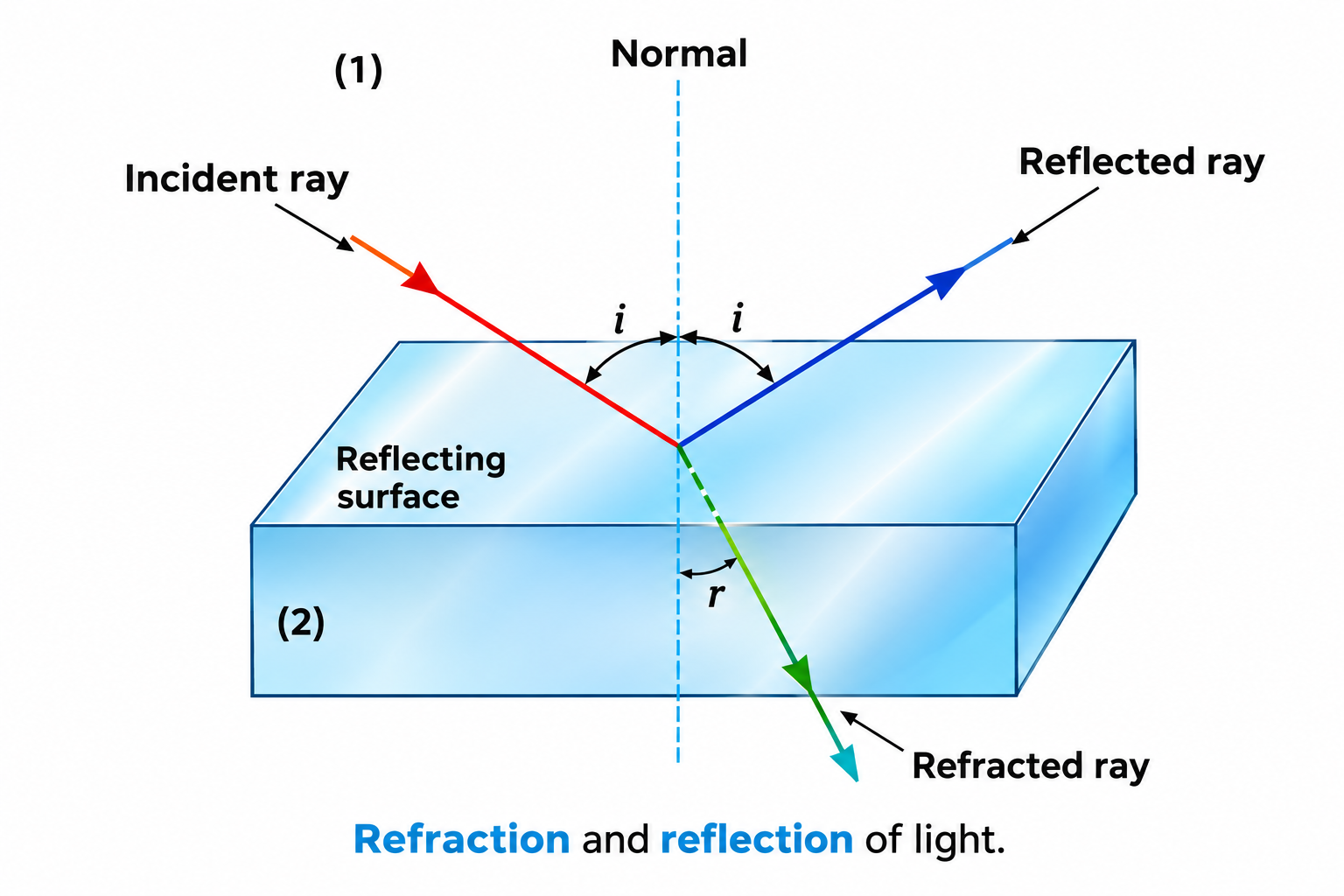
Figure 9.8: Refraction and reflection of light at a plane interface between two media.
3.1 Laws of Refraction
- The incident ray, the refracted ray, and the normal to the interface at the point of incidence all lie in the same plane.
- Snell's Law: The ratio of the sine of the angle of incidence ($i$) to the sine of the angle of refraction ($r$) is constant for a given pair of media and a given wavelength of light:
$$\mathbf{\frac{\sin i}{\sin r} = n_{21} = \frac{n_2}{n_1}}$$
Where $n_{21}$ is the relative refractive index of medium 2 with respect to medium 1.
3.2 Optical Density vs Mass Density
Absolute Refractive Index ($n$): The ratio of the speed of light in vacuum ($c$) to the speed of light in the medium ($v$):
$$\mathbf{n = \frac{c}{v} = \frac{\lambda_{vac}}{\lambda_{med}}}$$
- When light enters an optically denser medium ($n_2 > n_1$), its speed decreases ($v_2 < v_1$), and it bends towards the normal ($r < i$).
- When light enters an optically rarer medium ($n_2 < n_1$), its speed increases, and it bends away from the normal ($r > i$).
- Constant Frequency ($\nu$): During refraction, the frequency ($\nu$) of light remains unchanged (it is a property of the emitting source). The change in speed is entirely due to a change in wavelength ($\lambda = v/\nu$).
- Mass Density Distinction: Optical density is the ratio of speeds of light, which is distinct from mass density (mass per unit volume). Classic NCERT Example: The mass density of turpentine oil ($870\text{ kg/m}^3$) is less than water ($1000\text{ kg/m}^3$), but turpentine is optically denser ($n \approx 1.47$) than water ($n \approx 1.33$).
3.3 Relative Refractive Index & Multi-Interface Refraction
- Principle of Reversibility: If the path of a light ray is reversed, it exactly retraces its trajectory. Hence:
$$n_{12} = \frac{1}{n_{21}}$$
- Multiple Interfaces: For three media (1, 2, 3):
$$n_{32} = n_{31} \times n_{12} = \frac{n_{31}}{n_{21}} \implies {}^2n_3 = \frac{{}^1n_3}{{}^1n_2}$$
NCERT Exercise 9.4 • Multi-Interface Refraction
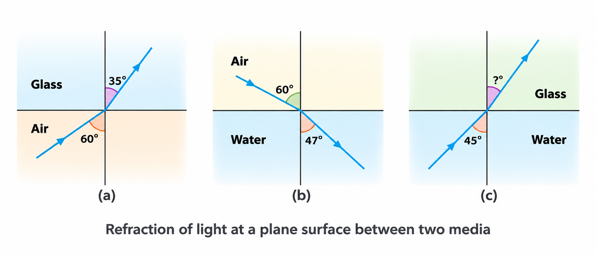
Figure 9.27: NCERT Exercise 9.4: Determining angle of refraction at water-glass interface using air-glass and air-water calibrations.
Problem: Using the calibrations given in Figure 9.27(a) [air-glass: $i=60^\circ, r=35^\circ$] and (b) [air-water: $i=60^\circ, r=47^\circ$], predict the angle of refraction in glass when a ray in water is incident at $45^\circ$ on the water-glass interface [Fig 9.27(c)].
Solution:
From (a): $n_g = \frac{\sin 60^\circ}{\sin 35^\circ} = \frac{0.8660}{0.5736} = 1.51$.
From (b): $n_w = \frac{\sin 60^\circ}{\sin 47^\circ} = \frac{0.8660}{0.7314} = 1.184$ (or $1.33$).
For water-glass interface: $n_w \sin 45^\circ = n_g \sin r \implies \sin r = \frac{n_w \sin 45^\circ}{n_g} = \frac{1.33 \times 0.7071}{1.51} \implies \mathbf{r \approx 38.2^\circ}$.
Derivation: Lateral Shift ($x$) in a Glass Slab
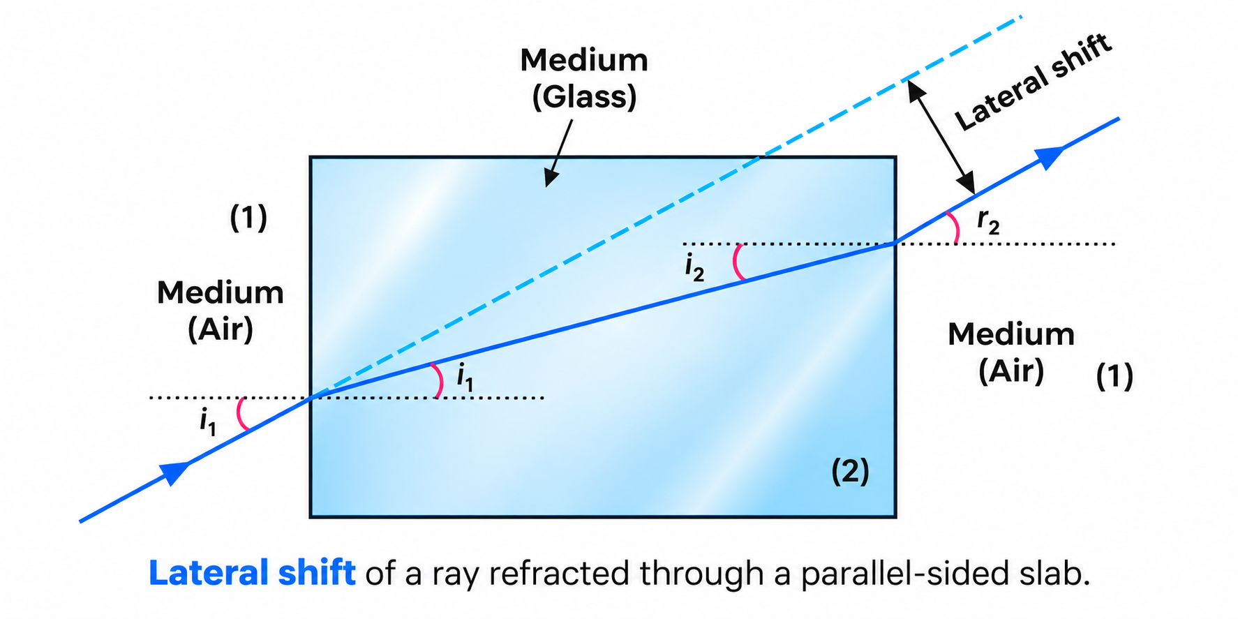
Figure 9.9: Lateral shift of a ray refracted through a parallel-sided glass slab.
Consider a rectangular glass slab of thickness $t$ and refractive index $n$. A ray of light is incident at angle $i_1$ on the top face and refracts at angle $r_1$. At the bottom face, the angle of incidence is $r_2 = r_1$, and the ray emerges into air at angle $r_2' = i_1$.
Emergent Ray Property: Since $r_2' = i_1$, the emergent ray is strictly
parallel to the incident ray (zero angular deviation).
However, the ray is laterally displaced by a perpendicular distance $x$. From the right-angled geometry of Figure 9.9:
$$\mathbf{x = \frac{t \sin(i - r)}{\cos r}}$$
Key Inferences: Lateral shift $x$ increases with:
- Increase in the thickness of the slab ($t$).
- Increase in the angle of incidence ($i$).
- Increase in the refractive index of the slab ($n$).
- Decrease in wavelength of light (violet suffers more lateral shift than red).
Apparent Depth & Normal Shift
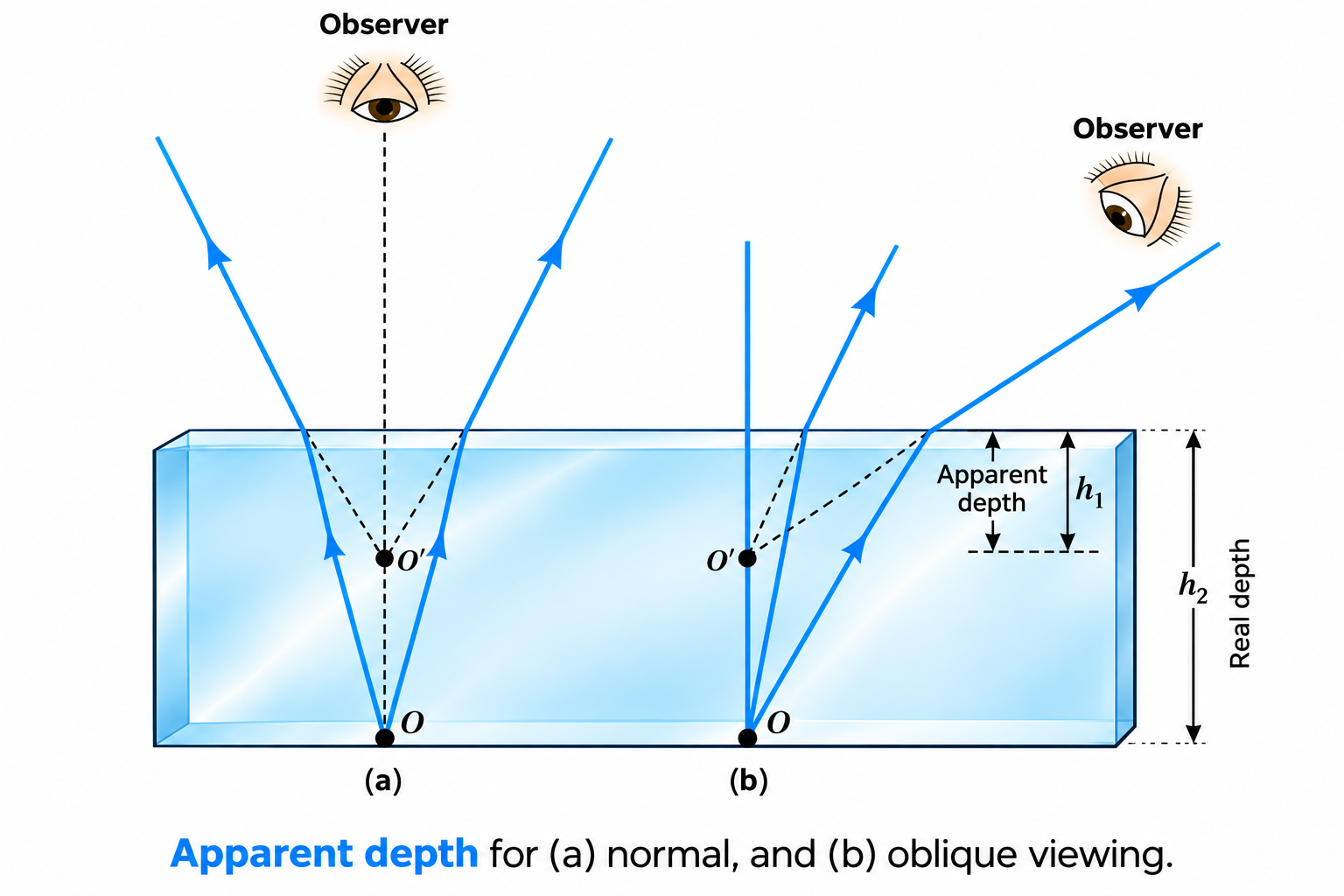
Figure 9.10: Apparent depth and upward normal shift for (a) normal viewing, and (b) oblique viewing.
When an object $O$ in an optically denser medium of refractive index $n$ is viewed from an optically rarer medium (air), rays bend away from the normal upon emerging, making the object appear raised at $I$.
For near-normal viewing ($\tan \theta \approx \sin \theta$):
$$\mathbf{\text{Apparent Depth } (h') = \frac{\text{Real Depth } (h)}{n}}$$
The vertical distance by which the object is shifted upward is called the
Normal Shift ($d$):
$$\mathbf{d = h - h' = t \left(1 - \frac{1}{n}\right)}$$
Multiple Liquid Layers: If a container is filled with immiscible liquids of thicknesses $t_1, t_2, \dots$ and indices $n_1, n_2, \dots$:
$$\text{Total Apparent Depth} = \frac{t_1}{n_1} + \frac{t_2}{n_2} + \dots \implies \mathbf{d_{total} = \sum t_i \left(1 - \frac{1}{n_i}\right)}$$
Inverse Case (Object in air viewed from water): An underwater diver looking at a flying bird sees the bird at an apparent height greater than real height: $\mathbf{h' = n \cdot h}$.
3.4 Atmospheric Refraction Phenomena
- Advance Sunrise and Delayed Sunset: The layers of the atmosphere become progressively denser and have higher refractive index closer to Earth. Sunlight entering obliquely bends continuously towards the normal. When the sun is physically just below the horizon, its rays bend and enter our eyes, making the sun visible $\approx 2\text{ minutes}$ before actual sunrise and $\approx 2\text{ minutes}$ after actual sunset. This increases the apparent length of a day by about $4\text{ minutes}$. The apparent shift in direction is $\approx 0.5^\circ$ ($30'$).
- Apparent Flattening of Sun at Sunrise/Sunset: Rays from the lower rim of the sun pass through more atmospheric layers and bend more than rays from the upper rim. This vertical compression gives the sun an oval, flattened appearance.
- Twinkling of Stars: Starlight travels through dynamic, turbulent atmospheric layers with constantly fluctuating temperatures and refractive indices. The apparent position and intensity of the point-like starlight fluctuate continuously.
4. Total Internal Reflection (TIR)
When light travels from an optically denser medium to an optically rarer medium, it bends away from the normal ($r > i$). As the angle of incidence $i$ increases, the angle of refraction $r$ increases until $r = 90^\circ$. If $i$ is increased further, no refraction is possible, and the entire incident light is reflected back into the denser medium. This is called Total Internal Reflection (TIR).
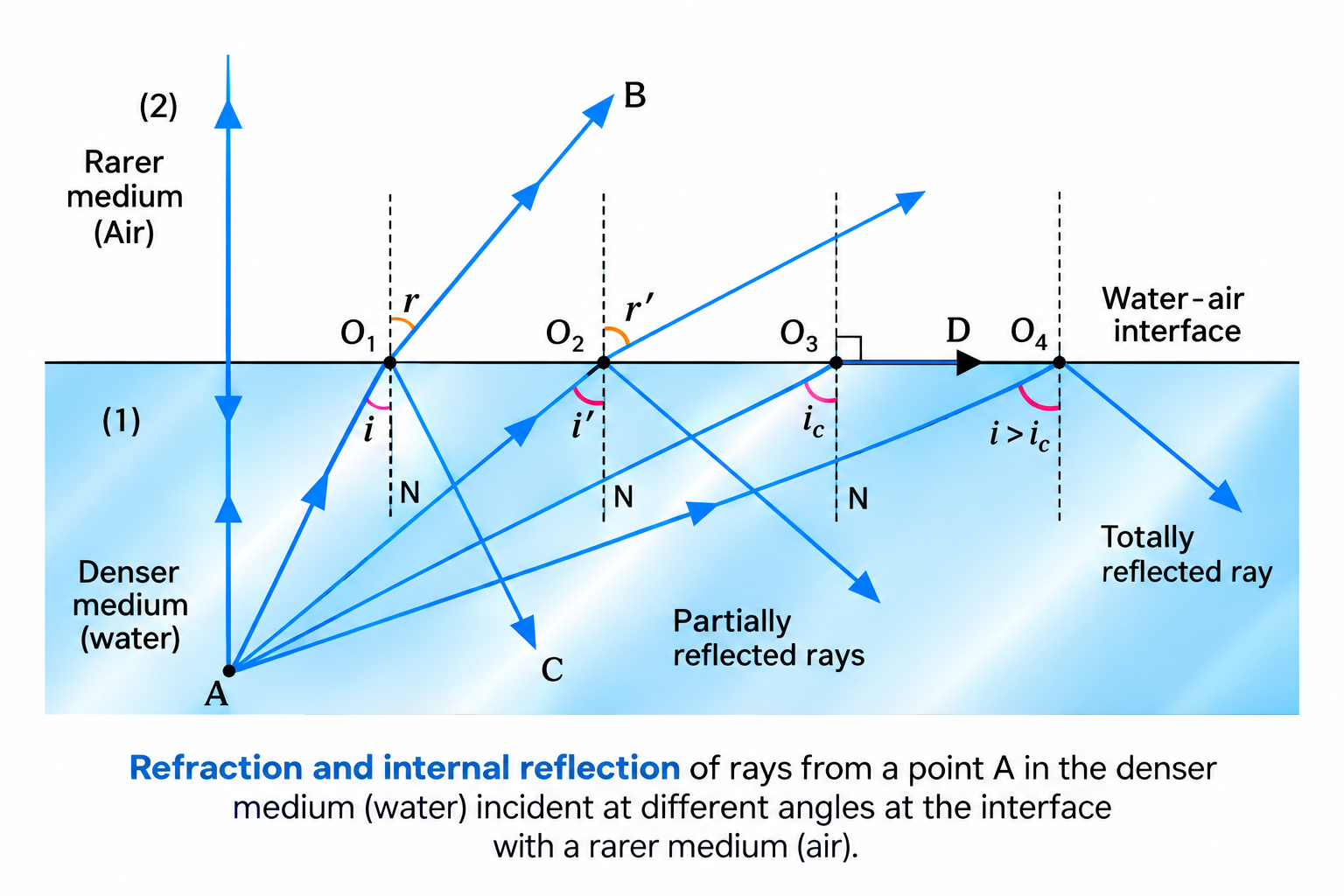
Figure 9.11: Refraction and total internal reflection of rays from a point A in a denser medium (water) incident at various angles at the interface with a rarer medium (air).
Two Mandatory Conditions for Total Internal Reflection
- Light must travel from an optically denser medium to an optically rarer medium.
- The angle of incidence ($i$) in the denser medium must be strictly greater than the critical angle ($i > i_c$) for the given pair of media.
4.1 Critical Angle ($i_c$)
The critical angle ($i_c$) is the angle of incidence in the denser medium for which the angle of refraction in the rarer medium is exactly $90^\circ$.
Applying Snell's Law at the interface ($n_1 \sin i_c = n_2 \sin 90^\circ$):
$$\mathbf{\sin i_c = \frac{n_2}{n_1} = n_{21}}$$
If the rarer medium 2 is air ($n_2 \approx 1$) and the denser medium has refractive index $n$:
$$\mathbf{\sin i_c = \frac{1}{n} \iff n = \frac{1}{\sin i_c}}$$
Table 9.1: Critical Angles of Common Media with Respect to Air
| Substance Medium |
Refractive Index ($n$) |
Critical Angle ($i_c$) |
| Water |
$1.33$ |
$48.75^\circ$ |
| Crown Glass |
$1.52$ |
$41.14^\circ$ |
| Dense Flint Glass |
$1.62$ |
$37.31^\circ$ |
| Diamond |
$2.42$ |
$24.41^\circ$ |
4.2 Demonstration of TIR with Laser in Water
📌 IMAGE REQUIRED • Images/Figure 9.12.png

Figure 9.12: Demonstration of total internal reflection using a laser beam in slightly turbid water: (a) partial refraction and reflection, (b) total internal reflection at water surface, and (c) multiple TIR along a long test tube.
4.3 Applications of Total Internal Reflection
- Mirage in Deserts: On hot summer days, ground heating creates a severe temperature gradient in air. Air near the ground is hot and less dense (optically rarer), while air higher up is cooler and denser. Rays from tall objects (like trees) travelling downward pass from denser to rarer layers, bending progressively away from the normal. When $i > i_c$, TIR occurs, and rays curve upward into the observer's eye. The observer perceives a virtual, inverted image below the ground, giving the illusion of a water pool reflecting the sky.
- Sparkling of Diamond: Diamond has an exceptionally high refractive index ($n \approx 2.42$) and a very small critical angle ($i_c \approx 24.41^\circ$). Master diamond cutters design the facets such that light entering the diamond strikes the internal faces at angles $> 24.41^\circ$. The light undergoes multiple internal reflections inside the diamond before emerging, resulting in dazzling brilliance.
- Totally Reflecting Prisms: Right-angled isosceles prisms ($45^\circ-90^\circ-45^\circ$) made of crown glass ($i_c \approx 41.14^\circ < 45^\circ$) utilize TIR:
- To bend rays through $90^\circ$ (used in periscopes).
- To bend rays through $180^\circ$ (used in binoculars and cameras).
- To invert an image without changing its size (erecting prisms).
- Advantage: 100% of the light intensity is reflected by TIR without the tarnishing, multiple ghost reflections, or absorption losses associated with silvered mirrors.
📌 IMAGE REQUIRED • Images/Figure 9.13.png

Figure 9.13: Totally reflecting prisms: (a) bending rays by \(90^\circ\), (b) bending rays by \(180^\circ\) (Porro prism), and (c) erecting an inverted image without changing size.
4.4 Optical Fibres
An optical fibre consists of a central glass/quartz Core of high refractive index ($n_1 \approx 1.68$) surrounded by a glass/plastic Cladding of slightly lower refractive index ($n_2 \approx 1.44$).
- Light launched into the core at an angle less than the acceptance angle strikes the core-cladding boundary at $i > i_c$.
- The light undergoes repeated total internal reflections along the entire length of the fibre with virtually zero energy leakage.
- Applications: High-speed telecommunication networks, medical endoscopes ("light pipes" for internal examination of stomach, esophagus, and intestines), and decorative lighting. Silica glass fibres can transmit over 95% of light across $1\text{ km}$.
📌 IMAGE REQUIRED • Images/Figure 9.14.png

Figure 9.14: Light undergoes successive total internal reflections as it propagates through the core of an optical fibre.
NCERT Exercise 9.17 • Light Pipe Acceptance Angle
📌 IMAGE REQUIRED • Images/Figure 9.28.png

Figure 9.28: NCERT Exercise 9.17: Acceptance angle cone and internal reflection geometry in a clad light pipe (\(n_1 = 1.68, n_2 = 1.44\)).
Problem: Figure 9.28 shows a cross-section of a 'light pipe' made of a glass fibre of refractive index $n_1 = 1.68$ and outer cladding $n_2 = 1.44$. What is the range of angles of incident rays with the axis of the pipe for which TIR takes place?
Solution:
At the core-cladding interface: $\sin i_c = \frac{n_2}{n_1} = \frac{1.44}{1.68} = 0.8571 \implies i_c = 59^\circ$.
For TIR inside: $i' \ge i_c = 59^\circ \implies r = 90^\circ - i' \le 31^\circ$.
At the front face entrance: $\sin i_{max} = n_1 \sin r_{max} = 1.68 \sin 31^\circ = 1.68 \times 0.5150 = 0.8652 \implies \mathbf{i_{max} \approx 60^\circ}$.
Thus, all rays incident within the range $\mathbf{0^\circ \le i \le 60^\circ}$ with the axis will suffer TIR.
5. Refraction at Spherical Surfaces and Thin Lenses
5-Mark Derivation: Refraction at a Single Spherical Surface
📌 IMAGE REQUIRED • Images/Figure 9.15.png

Figure 9.15: Refraction at a convex spherical surface separating rarer medium \(n_1\) from denser medium \(n_2\).
Consider a convex spherical surface of radius of curvature $R$ separating a rarer medium of refractive index $n_1$ from a denser medium of refractive index $n_2$. Let a point object $O$ be placed on the principal axis.
A ray $ON$ strikes the surface at $N$ and refracts along $NI$, meeting the principal axis at image point $I$. $NC$ is the normal to the surface passing through the center of curvature $C$.
Let $\angle NOM = \alpha$, $\angle NIM = \beta$, and $\angle NCM = \gamma$. Draw perpendicular $NM$ from $N$ to the principal axis.
For small paraxial angles ($\tan \theta \approx \theta$):
$$\alpha \approx \tan \alpha = \frac{MN}{OM}, \quad \beta \approx \tan \beta = \frac{MN}{MI}, \quad \gamma \approx \tan \gamma = \frac{MN}{MC}$$
In $\triangle NOC$, $i$ is the exterior angle: $i = \alpha + \gamma = \frac{MN}{OM} + \frac{MN}{MC}$.
In $\triangle NIC$, $\gamma$ is the exterior angle: $\gamma = r + \beta \implies r = \gamma - \beta = \frac{MN}{MC} - \frac{MN}{MI}$.
By Snell's Law for paraxial rays: $n_1 i = n_2 r$.
$$n_1 \left( \frac{MN}{OM} + \frac{MN}{MC} \right) = n_2 \left( \frac{MN}{MC} - \frac{MN}{MI} \right)$$
Dividing by $MN$ throughout and rearranging terms:
$$\frac{n_1}{OM} + \frac{n_2}{MI} = \frac{n_2 - n_1}{MC}$$
Applying Cartesian Sign Convention ($OM = -u, MI = +v, MC = +R$):
$$\mathbf{\frac{n_2}{v} - \frac{n_1}{u} = \frac{n_2 - n_1}{R}}$$
Note: This fundamental relation holds universally for any spherical interface (convex or concave), whether light travels from rarer to denser or denser to rarer (by swapping indices).
NCERT Example 9.5 • Spherical Surface Refraction
Problem: Light from a point source in air ($n_1 = 1.0$) falls on a convex spherical glass surface of refractive index $n_2 = 1.5$ and radius of curvature $R = +20\text{ cm}$. The light source is located at a distance of $100\text{ cm}$ from the glass surface. Find the position of the image formed.
Solution:
Given: $u = -100\text{ cm}$, $R = +20\text{ cm}$, $n_1 = 1$, $n_2 = 1.5$.
Using $\frac{n_2}{v} - \frac{n_1}{u} = \frac{n_2 - n_1}{R}$:
$$\frac{1.5}{v} - \frac{1}{-100} = \frac{1.5 - 1}{+20} \implies \frac{1.5}{v} + \frac{1}{100} = \frac{0.5}{20} = \frac{1}{40}$$
$$\frac{1.5}{v} = \frac{1}{40} - \frac{1}{100} = \frac{5 - 2}{200} = \frac{3}{200}$$
$$v = \frac{1.5 \times 200}{3} = \mathbf{+100\text{ cm}}$$
Conclusion: The real image is formed at a distance of $100\text{ cm}$ inside the glass in the direction of incident light.
5-Mark Derivation: Lens Maker's Formula & Thin Lens Equation
📌 IMAGE REQUIRED • Images/Figure 9.16.png

Figure 9.16: (a) Image formation by a thin double convex lens, (b) Refraction at the first surface \(ABC\), and (c) Refraction at the second surface \(ADC\).
Consider a thin lens bounded by two spherical surfaces $ABC$ (radius $R_1$) and $ADC$ (radius $R_2$) made of medium $n_2$ placed in a surrounding medium $n_1$.
Step 1: Refraction at First Interface ($ABC$):
Light travels from $n_1$ to $n_2$. The first surface forms an intermediate image $I_1$ at distance $v_1$:
$$\frac{n_2}{v_1} - \frac{n_1}{u} = \frac{n_2 - n_1}{R_1} \quad \text{--- (Eq. 1)}$$
Step 2: Refraction at Second Interface ($ADC$):
Light travels from $n_2$ to $n_1$. The intermediate image $I_1$ serves as a
virtual object for the second surface, forming the final image $I$ at distance $v$:
$$\frac{n_1}{v} - \frac{n_2}{v_1} = \frac{n_1 - n_2}{R_2} = -\frac{n_2 - n_1}{R_2} \quad \text{--- (Eq. 2)}$$
Step 3: Summing the Interface Equations:
Adding (Eq. 1) and (Eq. 2), the intermediate term $\frac{n_2}{v_1}$ cancels out:
$$\frac{n_1}{v} - \frac{n_1}{u} = (n_2 - n_1) \left( \frac{1}{R_1} - \frac{1}{R_2} \right)$$
Dividing throughout by $n_1$:
$$\frac{1}{v} - \frac{1}{u} = \left(\frac{n_2}{n_1} - 1\right) \left( \frac{1}{R_1} - \frac{1}{R_2} \right) \quad \text{--- (Eq. 3)}$$
Step 4: Defining Focus:
If the object is at infinity ($u = \infty$), the image is formed at the principal focus ($v = f$). Substituting $u = \infty, v = f$ into (Eq. 3) gives the
Lens Maker's Formula:
$$\mathbf{\frac{1}{f} = (n_{21} - 1) \left( \frac{1}{R_1} - \frac{1}{R_2} \right)}$$
Comparing (Eq. 3) and the Lens Maker's Formula yields the
Thin Lens Formula:
$$\mathbf{\frac{1}{v} - \frac{1}{u} = \frac{1}{f}}$$
Linear Magnification for a Lens:
$$\mathbf{m = \frac{h'}{h} = +\frac{v}{u} = \frac{f}{f + u} = \frac{f - v}{f}}$$
5.1 Rules for Ray Tracing through Lenses
To construct images formed by thin lenses, we use any two of the following standard rays:
📌 IMAGE REQUIRED • Images/Figure 9.17.png

Figure 9.17: Rules for tracing rays through (a) a convex lens, and (b) a concave lens.
- A ray parallel to the principal axis passes through the second focus $F'$ (convex lens) or appears to diverge from the first focus $F$ (concave lens).
- A ray passing through the optical center ($O$) emerges undeviated.
- A ray passing through the first focus $F$ (convex) or directed towards the second focus $F'$ (concave) emerges parallel to the principal axis.
5.2 Power of a Lens ($P$)
The power ($P$) of a lens is a measure of its ability to converge or diverge light rays falling on it. Quantitatively, it is defined as the tangent of the angle $\delta$ by which it converges or diverges a beam of light parallel to the principal axis falling at unit distance ($h = 1$) from the optical center:
📌 IMAGE REQUIRED • Images/Figure 9.18.png

Figure 9.18: Power of a lens defined by the deviation \(\delta\) of a parallel ray incident at unit height \(h = 1\).
$$\tan \delta = \frac{h}{f} \implies \text{For } h = 1 \text{ and small } \delta: \quad \mathbf{P = \frac{1}{f (\text{in meters})}}$$
- SI Unit: Dioptre ($\text{D}$), where $1\text{ D} = 1\text{ m}^{-1}$.
- Sign: $P > 0$ for a converging (convex) lens; $P < 0$ for a diverging (concave) lens.
- Example: A convex lens of $f = +40\text{ cm} = +0.4\text{ m}$ has power $P = +2.5\text{ D}$. A concave lens of $f = -25\text{ cm}$ has power $P = -4.0\text{ D}$.
Derivation: Combination of Thin Lenses in Contact
📌 IMAGE REQUIRED • Images/Figure 9.19.png

Figure 9.19: Image formation by a combination of two thin lenses A and B in contact.
Consider two thin lenses $A$ and $B$ of focal lengths $f_1$ and $f_2$ placed in coaxial contact.
For lens $A$: $\frac{1}{v_1} - \frac{1}{u} = \frac{1}{f_1}$.
For lens $B$ (using virtual intermediate image $I_1$ as object): $\frac{1}{v} - \frac{1}{v_1} = \frac{1}{f_2}$.
Adding both equations:
$$\frac{1}{v} - \frac{1}{u} = \frac{1}{f_1} + \frac{1}{f_2}$$
Replacing the combination with an equivalent lens of focal length $F$:
$$\mathbf{\frac{1}{F} = \frac{1}{f_1} + \frac{1}{f_2} + \frac{1}{f_3} + \dots}$$
In terms of power and magnification:
$$\mathbf{P = P_1 + P_2 + P_3 + \dots}$$
$$\mathbf{m = m_1 \times m_2 \times m_3 \times \dots}$$
NCERT Example 9.8 • Multi-Lens System
📌 IMAGE REQUIRED • Images/Figure 9.20.png

Figure 9.20: Ray tracing through a combination of three separated lenses (NCERT Example 9.8).
Problem: An object is placed at a distance of $30\text{ cm}$ in front of a combination of three lenses (Figure 9.20): $f_1 = +10\text{ cm}$, $f_2 = -10\text{ cm}$, and $f_3 = +30\text{ cm}$. The separation between lens 1 and lens 2 is $5\text{ cm}$, and between lens 2 and lens 3 is $10\text{ cm}$. Find the position of the final image.
Solution:
1. Image formed by 1st Lens ($f_1 = +10\text{ cm}, u_1 = -30\text{ cm}$):
$$\frac{1}{v_1} - \frac{1}{-30} = \frac{1}{10} \implies \frac{1}{v_1} = \frac{1}{10} - \frac{1}{30} = \frac{2}{30} \implies v_1 = +15\text{ cm}$$
2. Image formed by 2nd Lens ($f_2 = -10\text{ cm}$):
The image $I_1$ is at $(15 - 5) = +10\text{ cm}$ to the right of lens 2 (acting as a virtual object, $u_2 = +10\text{ cm}$):
$$\frac{1}{v_2} - \frac{1}{+10} = \frac{1}{-10} \implies \frac{1}{v_2} = -\frac{1}{10} + \frac{1}{10} = 0 \implies \mathbf{v_2 = \infty}$$
3. Image formed by 3rd Lens ($f_3 = +30\text{ cm}$):
Rays emerge parallel from lens 2, so for lens 3, $u_3 = -\infty$:
$$\frac{1}{v_3} - \frac{1}{-\infty} = \frac{1}{30} \implies \mathbf{v_3 = +30\text{ cm}}$$
Conclusion: The final real image is formed at $30\text{ cm}$ to the right of the third lens.
High-Yield Competitive Applications: Lens Alterations
1. Lens Immersed in a Medium:
$$\frac{f_m}{f_a} = \frac{(n_g - 1)}{\left(\frac{n_g}{n_m} - 1\right)}$$
- If $n_m < n_g$ (e.g., glass in water, $n_m = 4/3$): $f_{water} = 4 f_{air}$. Focal length quadruples; power drops to $1/4$.
- If $n_m = n_g$ (glass in liquid of same index, $n=1.47$): $1/f_m = 0 \implies f_m \to \infty$. The lens becomes completely invisible and acts like a plane glass plate (NCERT Example 9.6).
- If $n_m > n_g$ (glass in carbon disulfide): The term $\left(\frac{n_g}{n_m} - 1\right)$ becomes negative. The lens reverses its optical character (a convex lens behaves as a diverging lens!).
2. Cutting of a Lens:
- Vertical Transverse Cut: Cutting an equiconvex lens ($f$) along its vertical diameter produces two plano-convex lenses. $R_1 = R, R_2 = \infty \implies \mathbf{f' = 2f}$ and $\mathbf{P' = P/2}$.
- Horizontal Longitudinal Cut: Cutting a lens along its principal axis does not change the radii of curvature. Hence $\mathbf{f' = f}$. However, the aperture area is halved, so image intensity drops to half.
3. Silvering of One Surface: The system behaves as an equivalent mirror with power $P_{eq} = 2P_L + P_M \implies -\frac{1}{F_{eq}} = \frac{2}{f_L} - \frac{1}{f_M}$.
4. Displacement Method (Conjugate Foci): If a convex lens forms sharp images on a fixed screen for two positions separated by distance $d$, where object-screen distance is $D$:
$$\mathbf{f = \frac{D^2 - d^2}{4D}} \quad \text{and Object Height } \mathbf{h = \sqrt{h_1 h_2}} \quad (\text{Condition: } D \ge 4f)$$
Liquid Lens Method for Refractive Index (NCERT Exercise 9.31)
📌 IMAGE REQUIRED • Images/Figure 9.30.png

Figure 9.30: NCERT Exercise 9.31: Determining the refractive index of an unknown liquid using an equiconvex lens and plane mirror combination.
An equiconvex glass lens ($n_g = 1.5$) placed on a plane mirror with a liquid layer between them forms a combination of a convex glass lens and a plano-concave liquid lens.
If $f_1$ is the focal length of the convex lens alone and $F$ is the focal length of the combined system with liquid:
$$\frac{1}{F} = \frac{1}{f_1} + \frac{1}{f_{liquid}} \implies \mathbf{\frac{1}{f_{liquid}} = \frac{1}{F} - \frac{1}{f_1}}$$
Using the Lens Maker's formula for the plano-concave liquid lens ($\frac{1}{f_{liquid}} = (n_l - 1)\left(-\frac{1}{R}\right)$), the refractive index of the liquid $n_l$ is accurately calculated!
6. Refraction through a Prism and Dispersion
A prism is an optical element with two non-parallel refracting plane surfaces inclined at an angle $A$, called the angle of the prism (or refracting angle).
5-Mark Derivation: The Prism Formula
📌 IMAGE REQUIRED • Images/Figure 9.21.png

Figure 9.21: Ray path, angles of incidence, refraction, emergence, and angle of deviation \(\delta\) in a triangular glass prism.
In Figure 9.21, a ray $PQ$ strikes face $AB$ at angle of incidence $i$ and refracts at angle $r_1$. It travels through the prism along $QR$ and strikes face $AC$ at angle $r_2$, emerging along $RS$ at angle of emergence $e$.
1. In quadrilateral $AQNR$, $\angle AQ N = \angle ARN = 90^\circ$. Therefore:
$$\angle A + \angle QNR = 180^\circ \quad \text{--- (Eq. 1)}$$
2. In triangle $\triangle QNR$:
$$r_1 + r_2 + \angle QNR = 180^\circ \quad \text{--- (Eq. 2)}$$
Comparing (Eq. 1) and (Eq. 2):
$$\mathbf{r_1 + r_2 = A}$$
3. The total angle of deviation $\delta$ is the sum of deviations at both faces:
$$\delta = (i - r_1) + (e - r_2) = (i + e) - (r_1 + r_2)$$
$$\mathbf{\delta = i + e - A \iff A + \delta = i + e}$$
Condition for Minimum Deviation ($D_m$):
Experimentally and theoretically, at minimum deviation ($D_m$), the ray passes symmetrically through the prism, meaning:
$$i = e \quad \text{and} \quad r_1 = r_2 = r$$
The refracted ray inside the prism becomes strictly
parallel to the base.
Substituting these into our equations:
$$2r = A \implies \mathbf{r = \frac{A}{2}}$$
$$A + D_m = 2i \implies \mathbf{i = \frac{A + D_m}{2}}$$
Applying Snell's Law at the first interface gives the celebrated
Prism Formula:
$$\mathbf{n_{21} = \frac{\sin\left(\frac{A + D_m}{2}\right)}{\sin\left(\frac{A}{2}\right)}}$$
Thin Prism Deviation: For a small-angle prism ($A < 10^\circ$), $\sin \theta \approx \theta$:
$$n \approx \frac{(A + D_m)/2}{A/2} \implies \mathbf{D_m = (n - 1)A}$$
6.1 Angle of Deviation vs Angle of Incidence Curve
📌 IMAGE REQUIRED • Images/Figure 9.22.png

Figure 9.22: Plot of angle of deviation \(\delta\) versus angle of incidence \(i\) for a triangular prism, showing the unique minimum deviation \(D_m\).
6.2 Dispersion of Light
Dispersion: The phenomenon of splitting white light into its constituent spectral colors (VIBGYOR) when passing through a refracting medium.
- Physical Cause: The refractive index of any medium depends on the wavelength $\lambda$ of light, as given by Cauchy's Relation:
$$n(\lambda) = A + \frac{B}{\lambda^2} + \frac{C}{\lambda^4}$$
- Since $\lambda_{red} > \lambda_{violet}$, we have $n_{red} < n_{violet}$.
- From $\delta = (n - 1)A$, red light deviates the least and travels fastest in the medium, while violet light deviates the most.
- Angular Dispersion ($\theta$): The angular separation between extreme rays: $\mathbf{\theta = \delta_v - \delta_r = (n_v - n_r)A}$.
- Dispersive Power ($\omega$): The ratio of angular dispersion to mean deviation (yellow light):
$$\mathbf{\omega = \frac{\delta_v - \delta_r}{\delta_y} = \frac{n_v - n_r}{n_y - 1}}$$
6.3 Rainbow Formation (Natural Dispersion)
- Primary Rainbow: Formed by sunlight undergoing two refractions and one internal reflection inside suspended spherical raindrops. The observer sees a bright three-dimensional arc where red light emerges at $42^\circ$ (outer ring) and violet light emerges at $40^\circ$ (inner ring).
- Secondary Rainbow: Formed by sunlight undergoing two refractions and two internal reflections inside raindrops. Because of the extra internal reflection, the color order is reversed (violet at $53^\circ$ on the outside, red at $50^\circ$ on the inside), and the intensity is fainter.
7. Scattering of Light
When sunlight encounters gas molecules, dust, and aerosols in Earth's atmosphere, light energy is absorbed and re-radiated in all directions. This phenomenon is called scattering.
Rayleigh's Law of Scattering
If the diameter of the scattering particles ($a$) is much smaller than the wavelength of light ($a \ll \lambda$):
$$\mathbf{I \propto \frac{1}{\lambda^4}}$$
The intensity of scattered light is inversely proportional to the fourth power of its wavelength.
Natural Phenomena Explained by Scattering
- Blue Color of the Clear Sky: Blue light has a much shorter wavelength than red light ($\lambda_{red} \approx 1.8 \lambda_{blue}$). According to Rayleigh's law, blue light is scattered roughly $(1.8)^4 \approx 10\text{ to }15\text{ times}$ more strongly than red light by $N_2$ and $O_2$ molecules in the upper atmosphere. This scattered blue light reaches our eyes from every sky direction.
- Reddish Appearance of Sun at Sunrise and Sunset: At sunrise and sunset, sunlight travels through a maximum thickness of the atmosphere. The shorter wavelengths (blue/violet) are almost entirely scattered away sideways. Only the least scattered longer wavelengths (red and orange) penetrate the thick air column to reach our eyes directly.
- Why Danger Signals are Red: Red light has the longest wavelength in the visible band, suffering minimum Rayleigh scattering. Thus, red signals can penetrate smoke, fog, and dust over the longest distances without significant attenuation.
- White Appearance of Clouds: Clouds consist of large water droplets and ice crystals whose size $a \gg \lambda$. In this regime, Rayleigh's law breaks down, and Mie Scattering occurs, scattering all wavelengths equally. The uniform blend of all scattered visible wavelengths appears white.
8. Optical Instruments
8.1 The Simple Microscope (Magnifier)
A simple microscope is a converging (convex) lens of short focal length $f$. When a tiny object is placed between the optical center and the principal focus ($u \le f$), an erect, magnified, virtual image is formed on the same side as the object.
Simple Microscope Principle & Formulas
📌 IMAGE REQUIRED • Images/Figure 9.23.png

Figure 9.23: A simple microscope: (a) image formed at the near point \(D\), (b) visual angle subtended by object at near point without lens, and (c) object at focus with image formed at infinity (relaxed eye).
Angular Magnification / Magnifying Power ($m$): Defined as the ratio of the angle subtended by the image at the eye ($\beta$) to the angle subtended by the object at the unaided eye placed at the near point $D = 25\text{ cm}$ ($\alpha$):
$$m = \frac{\beta}{\alpha} \approx \frac{\tan \beta}{\tan \alpha}$$
- Case 1: Image at Near Point ($v = -D = -25\text{ cm}$ • Maximum Strain):
$$\mathbf{m = 1 + \frac{D}{f}}$$
- Case 2: Normal Adjustment (Image at Infinity $v = \infty$ • Relaxed Eye):
$$\mathbf{m = \frac{D}{f}}$$
8.2 The Compound Microscope
To achieve high magnifications ($\gg 9\times$), a compound microscope uses two converging lenses in series:
- Objective Lens ($O$): Faces the object. Has a very short focal length ($f_o$) and small aperture to produce a real, inverted, magnified intermediate image $A'B'$.
- Eyepiece ($E$): Positioned near the eye. Has a short focal length ($f_e$) (with $f_e > f_o$) and larger aperture. It acts as a simple magnifier on the intermediate image $A'B'$ to produce a highly enlarged virtual final image $A''B''$.
- Tube Length ($L$): The separation distance between the second focal point of the objective and the first focal point of the eyepiece.
5-Mark Derivation: Compound Microscope Magnifying Power
📌 IMAGE REQUIRED • Images/Figure 9.24.png

Figure 9.24: Complete ray diagram for image formation in a compound microscope.
The total magnification is the product of linear magnification of objective ($m_o$) and angular magnification of eyepiece ($m_e$):
$$m = m_o \times m_e$$
From Figure 9.24, the linear magnification produced by the objective is:
$$m_o = \frac{h'}{h} \approx -\frac{L}{f_o} \quad \left(\text{or } m_o = -\frac{v_o}{u_o}\right)$$
Case 1: Final Image at Least Distance of Distinct Vision ($D = 25\text{ cm}$):
$$m_e = 1 + \frac{D}{f_e} \implies \mathbf{m = -\left(\frac{L}{f_o}\right) \left(1 + \frac{D}{f_e}\right) \approx -\left(\frac{v_o}{u_o}\right)\left(1 + \frac{D}{f_e}\right)}$$
Total separation between lenses: $\mathbf{L_{tube} = v_o + u_e}$
Case 2: Normal Adjustment (Final Image at Infinity • Relaxed Eye):
$$m_e = \frac{D}{f_e} \implies \mathbf{m = -\left(\frac{L}{f_o}\right) \left(\frac{D}{f_e}\right) \approx -\left(\frac{v_o}{u_o}\right)\left(\frac{D}{f_e}\right)}$$
Total separation between lenses: $\mathbf{L_{tube} = v_o + f_e}$
Design Rule: For large magnification, both $f_o$ and $f_e$ must be made very small, with $f_o < f_e$.
8.3 Astronomical Telescope (Refracting Type)
Used to view distant heavenly objects (stars, planets). It consists of two coaxial convex lenses:
- Objective Lens ($O$): Must have a large focal length ($f_o$) and a very large aperture to gather maximum light from faint distant sources and provide high resolving power.
- Eyepiece ($E$): Has a short focal length ($f_e$) and small aperture to provide high magnification.
Astronomical Telescope Ray Diagram & Formulas
📌 IMAGE REQUIRED • Images/Figure 9.25.png

Figure 9.25: Ray diagram of an astronomical refracting telescope in normal adjustment (image at infinity).
Magnifying power ($m$) is the ratio of angle subtended by the final image at the eye ($\beta$) to angle subtended by the distant object at the objective ($\alpha$):
$$m = \frac{\beta}{\alpha}$$
- Normal Adjustment (Final Image at Infinity • Relaxed Eye):
$$\mathbf{m = \frac{f_o}{f_e}} \quad \text{and Tube Length } \mathbf{L = f_o + f_e}$$
- Final Image at Near Point ($D = 25\text{ cm}$):
$$\mathbf{m = \frac{f_o}{f_e} \left(1 + \frac{f_e}{D}\right)} \quad \text{and Tube Length } \mathbf{L = f_o + u_e}$$
8.4 Reflecting Telescopes (Cassegrain Telescope)
To overcome the severe physical and optical limitations of giant glass lenses, modern astronomical observatories use reflecting telescopes with curved mirror objectives.
📌 IMAGE REQUIRED • Images/Figure 9.26.png

Figure 9.26: Schematic diagram of a Cassegrain reflecting telescope using a primary concave mirror and secondary convex mirror.
Major Advantages of Reflecting Telescopes over Refracting Telescopes (CBSE Favorite)
- No Chromatic Aberration: Lenses suffer from chromatic aberration due to dispersion of light into constituent wavelengths. Mirrors reflect all wavelengths equally according to the law of reflection, entirely eliminating chromatic distortion.
- No Spherical Aberration: By utilizing a paraboloidal primary mirror, all parallel incident rays converge precisely to a single focus, completely eliminating spherical aberration.
- Full Mechanical Support: A huge glass lens can only be clamped and supported around its thin outer rim, causing heavy glass disks to sag and distort under gravity. A mirror can be supported continuously across its entire rear surface.
- High Resolving Power at Lower Cost: Making a large lens requires grinding and polishing two flawless surfaces without internal bubbles or strains. A reflector requires polishing only a single front surface, making giant apertures feasible (e.g., $2.34\text{ m}$ Vainu Bappu Telescope at Kavalur, India; $10\text{ m}$ Keck Telescopes in Hawaii).
9. NCERT Points to Ponder (Conceptual Distinctions)
Conceptual Mastery
- Image Suspended in Air: A real image formed by a lens or mirror exists in physical space even if no screen is placed there. A screen simply scatters light diffusely in all directions so that multiple observers can view it. Without a screen, an observer placed in the path of the converging/diverging cone of rays can still see the image directly.
- Regular vs Diffuse Reflection: Regular reflection produces point-to-point image correspondence. Diffuse reflection from a rough paper surface scatters light in all directions, illuminating the page without forming an image of the source.
- Thick Lens Dispersion: Thick lenses produce chromatic aberration because their edges behave like prisms with different focal lengths for different colors.
- Angular Magnification vs Linear Size: A simple microscope does not actually change the physical size of the object; it allows the object to be positioned closer than the near point ($25\text{ cm}$), thereby dramatically increasing the visual angle subtended at the retina.
