
Dear Class 12 Student! Electrostatics (Chapters 1 & 2) was all about charges at rest. Chapter 3 got them moving. Now, we uncover the grand secret of the universe: Moving charges create Magnetic Fields! This chapter bridges electricity and magnetism, paving the way for Electromagnetism. The Biot-Savart Law and Ampere's Law derivations here are guaranteed 5-markers in your board exams. Let's conquer them!
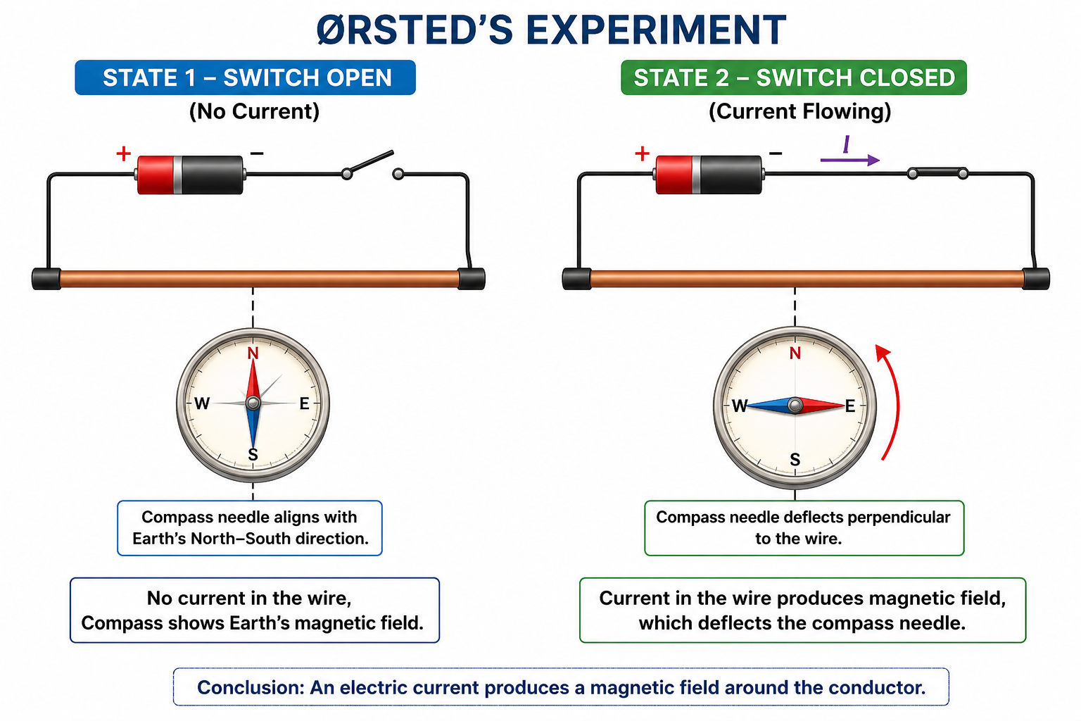
Oersted's Experiment: In 1820, Hans Christian Oersted observed that a magnetic compass needle deflected when placed near a current-carrying wire. This monumental discovery proved that moving charges (current) produce a magnetic field.
Magnetic Field ($\vec{B}$): The space around a magnet or a moving charge where its magnetic influence can be felt. It is a vector quantity. Its SI unit is the Tesla ($T$) or Weber/meter$^2$ ($Wb/m^2$).
If a charge $q$ moves with velocity $\vec{v}$ in a uniform magnetic field $\vec{B}$, it experiences a magnetic force $\vec{F}_m$:
Conditions for Zero Force ($F_m = 0$):
1. Fleming's Left-Hand Rule: Stretch the thumb, forefinger, and middle finger of your left hand mutually perpendicular. If the Forefinger points to the Field ($\vec{B}$) and the Middle finger points to the Current (Velocity of positive charge $\vec{v}$), then the Thumb points to the Force ($\vec{F}$).
2. Right-Hand Palm Rule: Open your right hand. Point fingers in direction of $\vec{B}$, thumb in direction of $\vec{v}$ (for positive charge). The palm faces the direction of Force ($\vec{F}$).
Note: If the charge is negative (like an electron), reverse the final direction of the force!If a charge $q$ is moving in a region where BOTH electric field $\vec{E}$ and magnetic field $\vec{B}$ exist, the total force is the vector sum of electric and magnetic forces:
$$\vec{F} = \vec{F}_e + \vec{F}_m = q\vec{E} + q(\vec{v} \times \vec{B})$$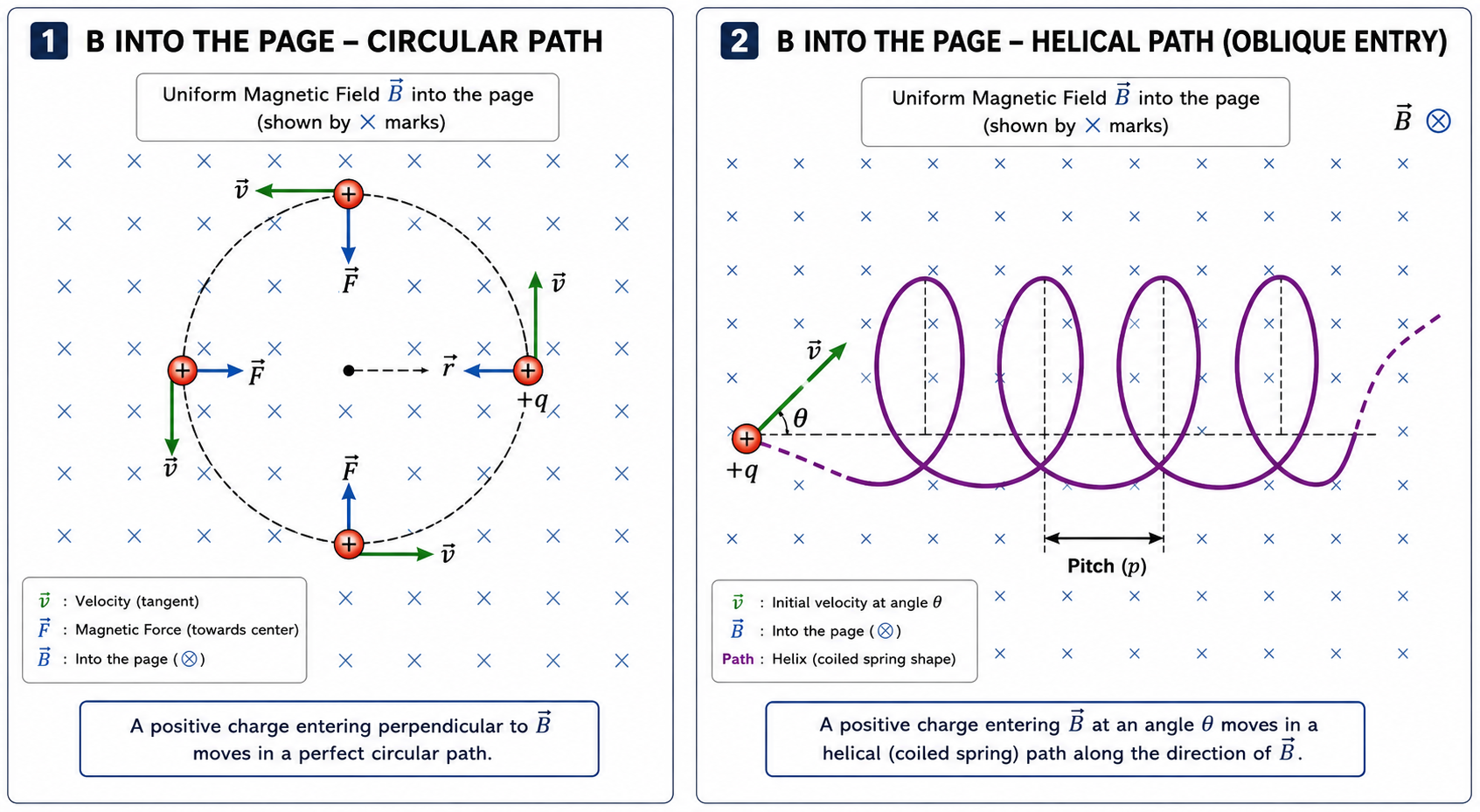
When $\vec{v}$ is perpendicular to $\vec{B}$, the magnetic force $\vec{F} = q(\vec{v} \times \vec{B})$ is always perpendicular to the velocity. This force acts as a Centripetal Force, making the particle move in a Circular Path.
1. Radius of Circular Path ($r$):
Centripetal Force = Magnetic Force
$\frac{mv^2}{r} = qvB \implies$ $$r = \frac{mv}{qB}$$
2. Time Period ($T$) and Frequency ($\nu$):
Time taken for one revolution: $T = \frac{2\pi r}{v}$
Substitute $r$: $T = \frac{2\pi}{v} \left( \frac{mv}{qB} \right) \implies$ $$T = \frac{2\pi m}{qB}$$
Frequency $\nu = \frac{1}{T} \implies$ $$\nu = \frac{qB}{2\pi m}$$
Crucial Fact: The time period and frequency are completely independent of velocity and radius! A faster particle moves in a larger circle, but takes the exact same amount of time to complete one revolution.
3. Kinetic Energy ($KE$):
From radius formula, $v = \frac{qBr}{m}$.
$KE = \frac{1}{2}mv^2 = \frac{1}{2}m \left( \frac{qBr}{m} \right)^2 \implies$ $$KE = \frac{q^2 B^2 r^2}{2m}$$
Resolve the velocity $\vec{v}$ into two components:
1. $v_{\perp} = v\sin\theta$: Perpendicular to $\vec{B}$. This makes the particle go in a circle.
2. $v_{\parallel} = v\cos\theta$: Parallel to $\vec{B}$. This experiences no force and pulls the particle straight forward uniformly.
The combination of circular and straight-line motion results in a Helical Path.
Pitch of the Helix ($p$): The linear distance traveled along the magnetic field in one complete rotation.
Pitch = $v_{\parallel} \times T = (v\cos\theta) \times \left( \frac{2\pi m}{qB} \right) \implies$ $$p = \frac{2\pi m v \cos\theta}{qB}$$
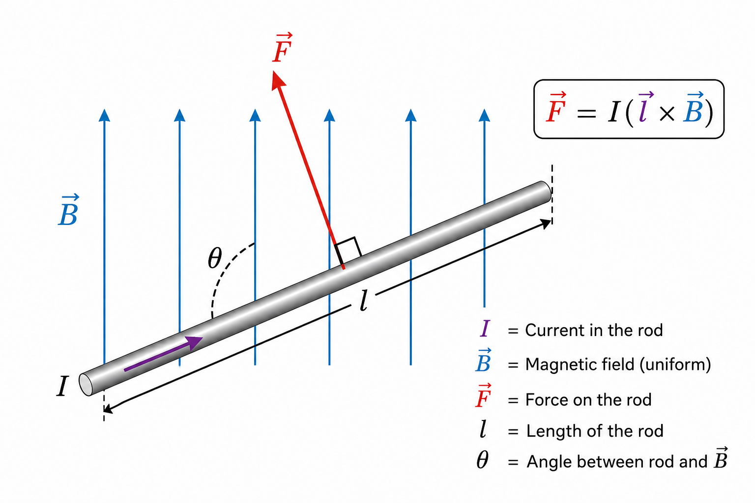
Since current is a flow of moving charges, a wire carrying current in a magnetic field experiences a force.
Derivation: Let a wire of length $l$, area $A$, and electron density $n$ carry current $I$.
Total number of free electrons = $nAl$.
Force on one electron $f = e(v_d \times B)$ (where $v_d$ is drift velocity).
Total force on wire $F = (nAl) \times e(v_d B \sin\theta) = (neAv_d) l B \sin\theta$.
Since $I = neAv_d$, we get:
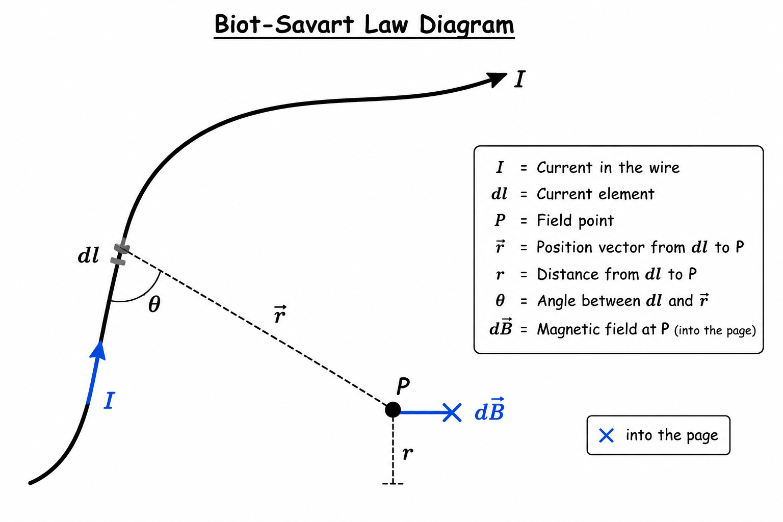
This is the fundamental law to calculate the magnetic field produced by an infinitesimally small current element.
Permeability of Free Space ($\mu_0$): The constant of proportionality.
Value: $\mu_0 = 4\pi \times 10^{-7} \text{ T}\cdot\text{m/A}$.
Dimensions: $[MLT^{-2}A^{-2}]$.
Comparison with Coulomb's Law:
- Similarities: Both are inverse square laws ($1/r^2$). Both obey superposition.
- Differences: Electrostatic field is produced by a scalar source ($q$), magnetic field by a vector source ($Id\vec{l}$). Electrostatic field acts along the displacement vector, while magnetic field acts perpendicular to the plane containing $d\vec{l}$ and $\vec{r}$. Magnetic field has an angle dependence ($\sin\theta$), electric field does not.
For a circular loop of radius $R$ carrying current $I$, the angle $\theta$ between any $dl$ element and the radius vector $r$ is always $90^\circ$.
$B = \int dB = \int \frac{\mu_0 I dl \sin 90^\circ}{4\pi R^2} = \frac{\mu_0 I}{4\pi R^2} \int dl$.
Since $\int dl = 2\pi R$ (circumference):
$$B = \frac{\mu_0 I}{2R}$$ (For $N$ turns, multiply by $N$).
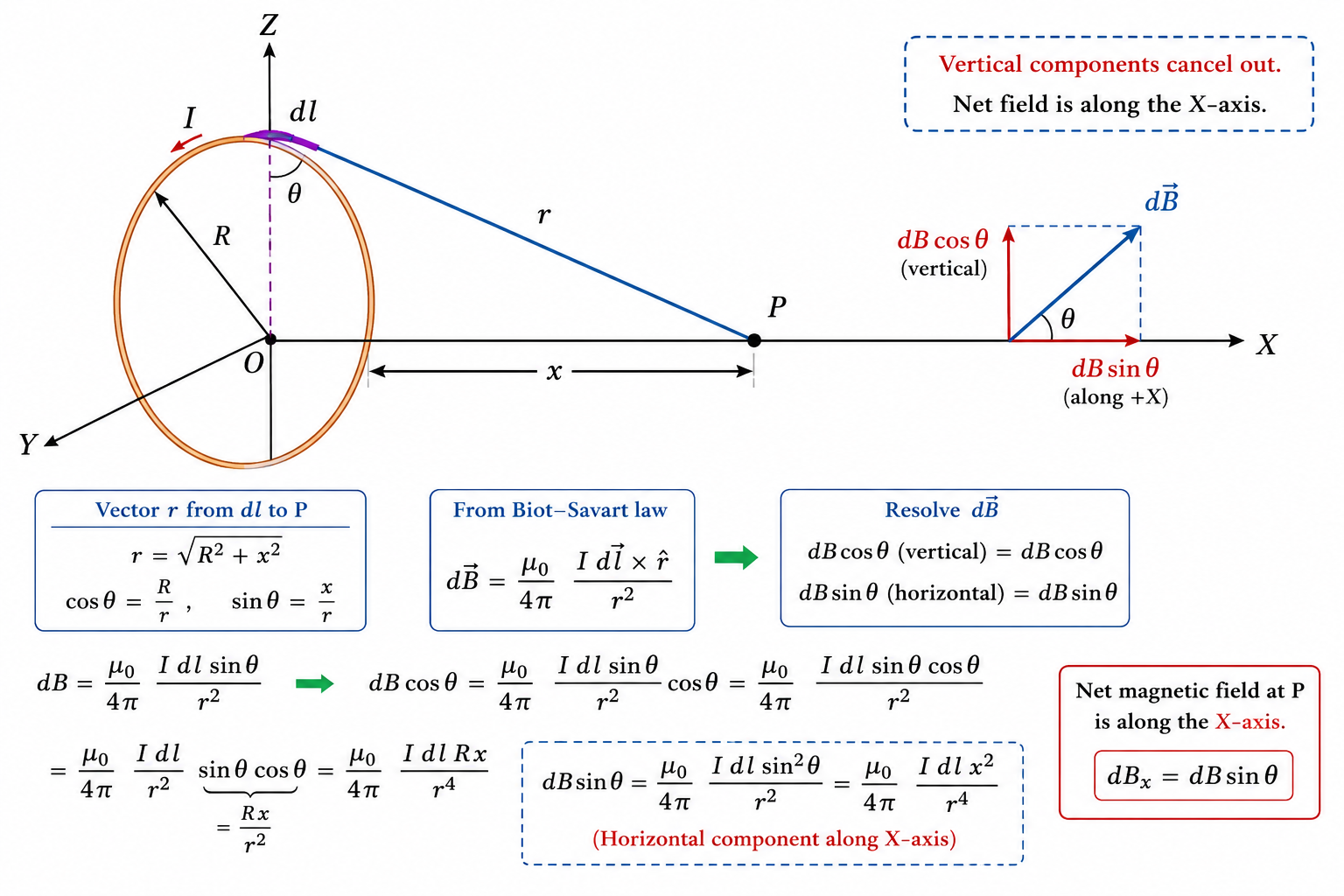
Derivation: Consider a circular loop of radius $R$ carrying current $I$. We want to find the field at point P on the axis at distance $x$ from the center.
Distance of P from current element $dl$ is $r = \sqrt{R^2 + x^2}$.
The field due to $dl$ is $dB = \frac{\mu_0 I dl}{4\pi r^2}$ (since angle between $dl$ and $r$ is $90^\circ$ in 3D space).
Resolving $dB$: The perpendicular components ($dB \cos\phi$) from diametrically opposite elements cancel out. Only the axial components ($dB \sin\phi$) add up.
$B_{net} = \int dB \sin\phi$. From geometry, $\sin\phi = \frac{R}{r} = \frac{R}{\sqrt{R^2+x^2}}$.
$B_{net} = \int \left( \frac{\mu_0 I dl}{4\pi (R^2+x^2)} \right) \left( \frac{R}{\sqrt{R^2+x^2}} \right) = \frac{\mu_0 I R}{4\pi (R^2+x^2)^{3/2}} \int dl$.
Substituting $\int dl = 2\pi R$:
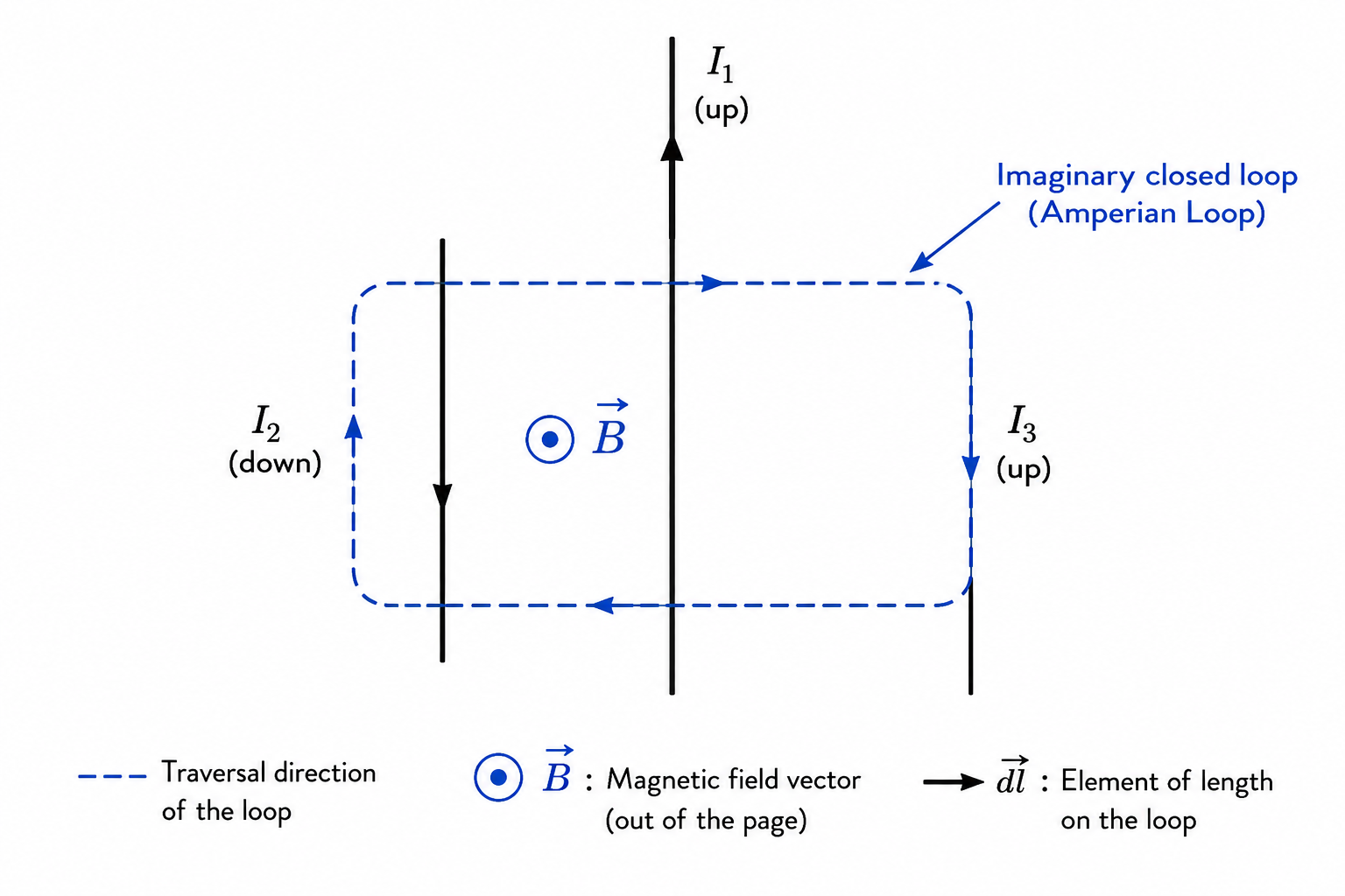
Just as Gauss's Law provides an easier alternative to Coulomb's Law for highly symmetric charge distributions, Ampere's Circuital Law provides an elegant alternative to the Biot-Savart Law for highly symmetric current distributions.
Sign Convention (Right-Hand Rule): Curl the fingers of your right hand in the direction you are integrating (traversing) around the Amperian loop. The direction of your thumb determines the positive direction for current. Currents flowing in the direction of the thumb are $+I$, and opposite are $-I$.
Consider an infinite straight wire carrying current $I$. We construct a circular Amperian loop of radius $r$ around it.
By symmetry, $\vec{B}$ is constant in magnitude on the loop and tangent to it everywhere ($\vec{B} \parallel d\vec{l}$, so $\cos 0^\circ = 1$).
$\oint \vec{B} \cdot d\vec{l} = B \oint dl = B(2\pi r)$.
By Ampere's Law: $B(2\pi r) = \mu_0 I \implies$ $$B = \frac{\mu_0 I}{2\pi r}$$
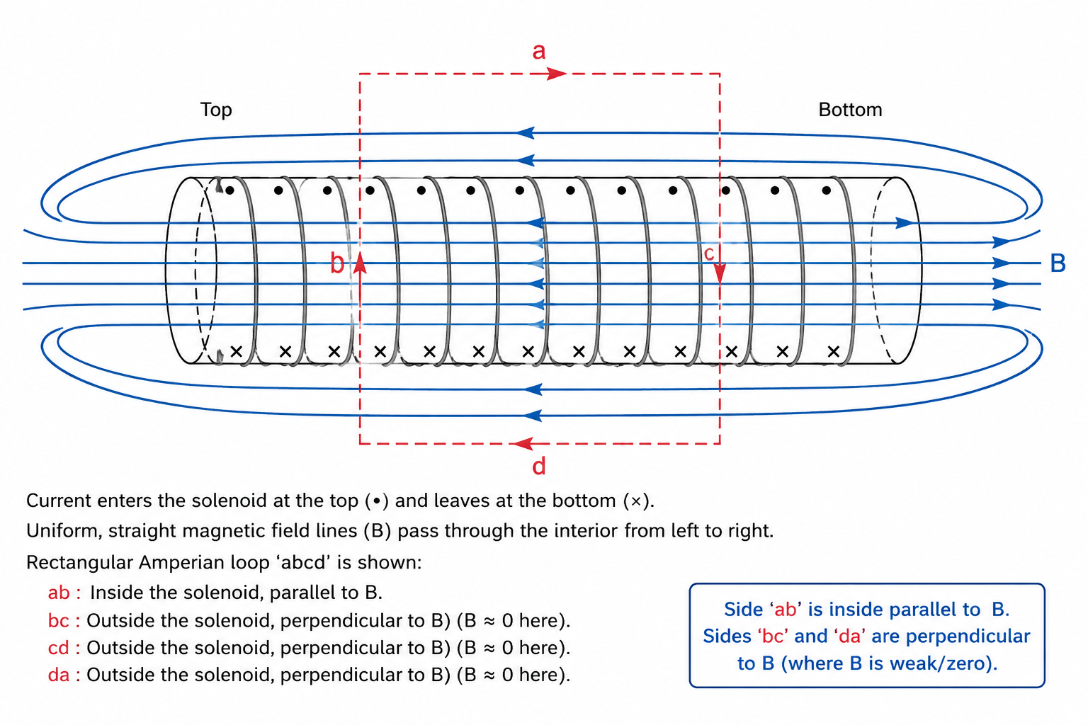
A solenoid is a long coil of wire tightly wound in a helix. Inside an ideal long solenoid, the magnetic field is uniform and strong. Outside, it is negligibly weak ($B_{out} \approx 0$).
Derivation: Consider a rectangular Amperian loop $abcd$. Length $ab = L$ lies inside.
$\oint \vec{B} \cdot d\vec{l} = \int_a^b B \cdot dl + \int_b^c B \cdot dl + \int_c^d B \cdot dl + \int_d^a B \cdot dl$
- Paths $bc$ and $da$ are perpendicular to $\vec{B}$, so dot product is 0.
- Path $cd$ is outside, where $B = 0$.
- Only path $ab$ survives: $\int_a^b B \cdot dl = B \times L$.
Enclosed current: If $n$ is the number of turns per unit length, total turns enclosed = $nL$. Total current = $(nL)I$.
By Ampere's Law: $B L = \mu_0 (nL)I \implies$
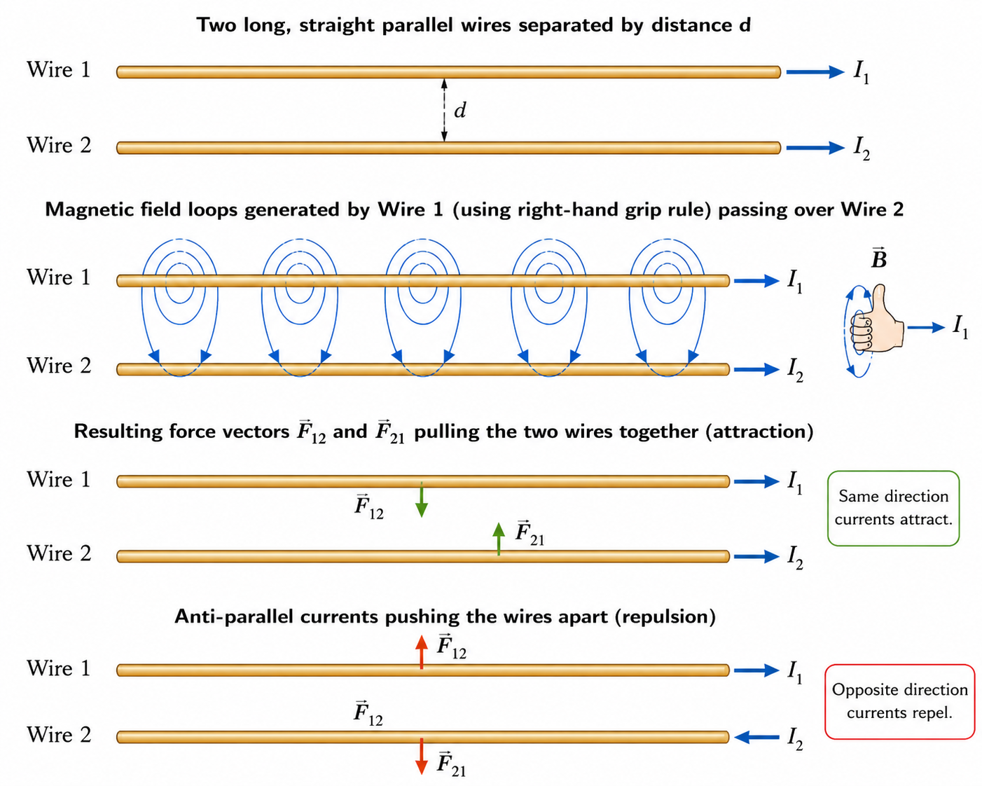
Derivation (Very Important for Boards):
Let Wire 1 and Wire 2 be parallel, separated by distance $d$, carrying currents $I_1$ and $I_2$.
Wire 1 creates a magnetic field at the location of Wire 2. From Ampere's Law: $B_1 = \frac{\mu_0 I_1}{2\pi d}$.
Now, Wire 2 (carrying current $I_2$ of length $L$) sits in this magnetic field $B_1$.
The force on Wire 2 is $F_2 = I_2 L B_1 \sin 90^\circ = I_2 L \left( \frac{\mu_0 I_1}{2\pi d} \right)$.
Force per unit length ($f = F/L$):
Standard Definition of the Ampere (Must-Know Board Question):
One Ampere is defined as that constant current which, if maintained in two straight parallel conductors of infinite length, of negligible circular cross-section, and placed 1 meter apart in a vacuum, would produce between these conductors a force equal to $2 \times 10^{-7}$ Newtons per meter of length.
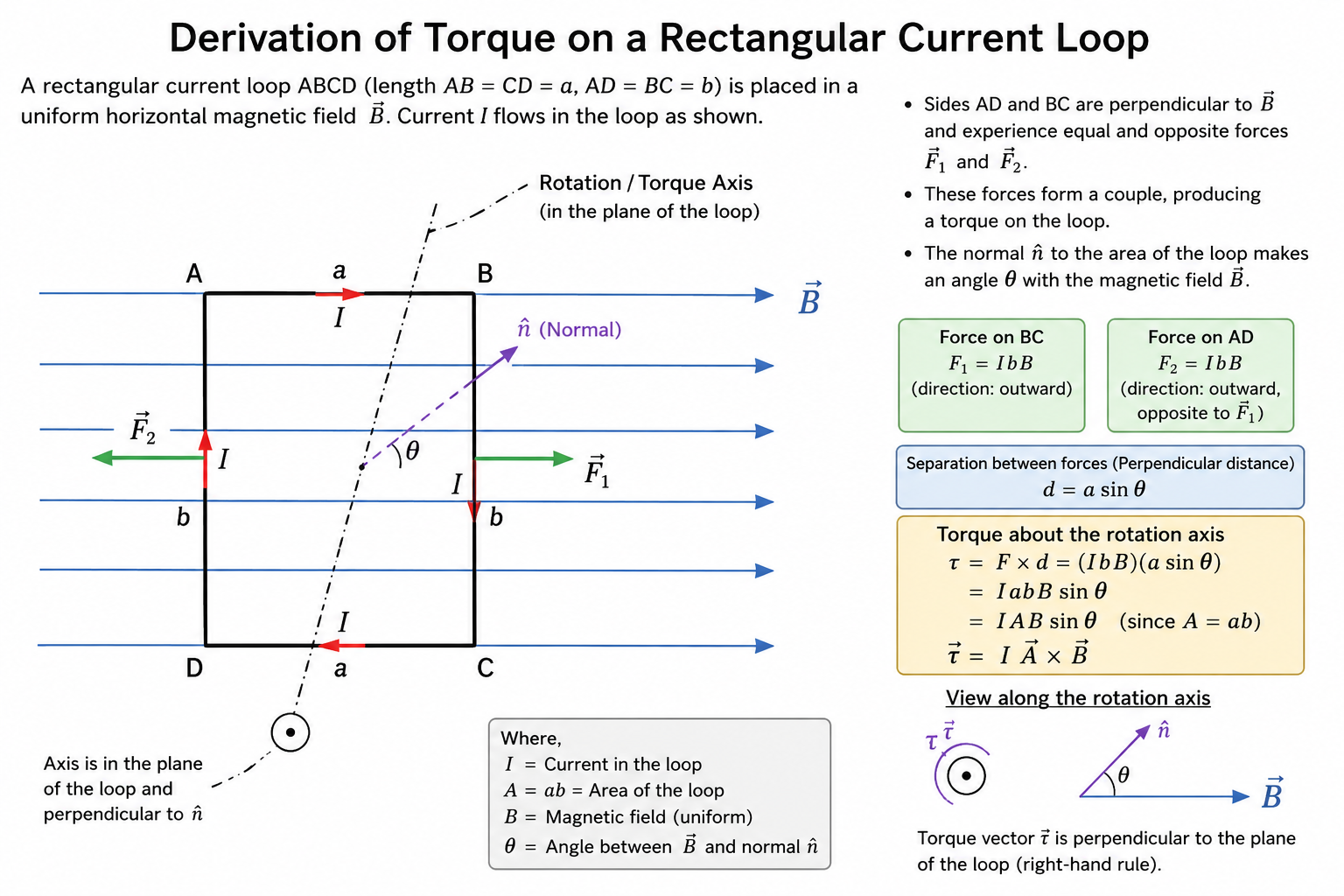
When a rectangular loop carrying current $I$ is placed in a uniform magnetic field $\vec{B}$, the forces on the arms parallel to the axis of rotation cancel out, but the forces on the perpendicular arms form a Couple, exerting a torque.
Derivation: Let the loop have length $l$ and breadth $b$. Area $A = l \times b$.
Force on vertical arms = $F = I l B$.
Perpendicular distance between these forces = $b \sin\theta$ (where $\theta$ is the angle between the normal to the area and the magnetic field).
Torque $\tau = \text{Force} \times \text{Perpendicular distance} = (I l B) \times (b \sin\theta) = I (l \times b) B \sin\theta$.
For a coil with $N$ turns:
Just like an electric dipole $\vec{p}$ experiences torque $\vec{\tau} = \vec{p} \times \vec{E}$, a current loop acts like a Magnetic Dipole.
Definition: $\vec{m} = NI\vec{A}$.
SI Unit: $A\cdot m^2$.
Using this, torque can be elegantly written as: $$\vec{\tau} = \vec{m} \times \vec{B}$$
An electron revolving in a circular orbit of radius $r$ with velocity $v$ acts as a tiny current loop.
Current $I = \frac{e}{T} = \frac{e}{2\pi r / v} = \frac{ev}{2\pi r}$.
Magnetic moment $m = I \times A = \left( \frac{ev}{2\pi r} \right) \times (\pi r^2) = \frac{evr}{2}$.
Multiply and divide by mass of electron ($m_e$): $m = \frac{e(m_e v r)}{2m_e}$.
Since $m_e v r = L$ (Angular Momentum), we get: $\vec{m} = -\frac{e}{2m_e} \vec{L}$.
Bohr Magneton ($\mu_B$): The minimum magnetic dipole moment associated with an electron (when $n=1$ in Bohr's model, $L = h/2\pi$).
$\mu_B = \frac{eh}{4\pi m_e} = 9.27 \times 10^{-24} \text{ A}\cdot\text{m}^2$.
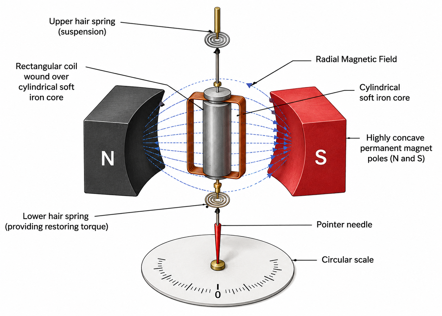
Principle: A current-carrying coil placed in a uniform magnetic field experiences a torque.
Construction & Radial Magnetic Field: The galvanometer uses highly concave pole pieces and a soft iron core. This combination produces a Radial Magnetic Field. In a radial field, the plane of the coil is always parallel to the magnetic field, regardless of its rotation. This means $\theta = 90^\circ$ always, so $\sin 90^\circ = 1$. The torque is always maximum: $\tau_d = NIAB$.
Working and Theory:
Deflecting torque $\tau_d = NIAB$.
As the coil rotates, a hairspring provides a restoring torque proportional to the angle of twist $\phi$.
Restoring torque $\tau_r = k\phi$ (where $k$ is torsional constant of the spring).
In equilibrium: $NIAB = k\phi$
$$\phi = \left(\frac{NAB}{k}\right)I$$
The term in the bracket is constant, meaning the deflection $\phi$ is directly proportional to current $I$, giving a linear scale!
Connecting back to Chapter 3 concepts: