Vardaan Learning Institute
Class 12 Physics • Chapter Notes
🌐 vardaanlearning.com📞 9508841336
Class 12 Physics: Current Electricity (Class Notes)
Dear Class 12 Student! Chapters 1 and 2 dealt with charges at rest (Electrostatics). Now, we set those charges into motion. Current Electricity is one of the highest-weightage chapters in both CBSE Boards and JEE Main. The derivations of Drift Velocity and Ohm's Law are almost guaranteed board questions, while Kirchhoff's rules and instrument-based problems dominate competitive exams. Let's conquer it!
1. Electric Current and Flow of Charges
Electric Current ($I$): It is defined as the rate of flow of electric charge through any cross-section of a conductor.
Formula & Units
If charge $\Delta q$ flows in time $\Delta t$, the average current is $I_{avg} = \frac{\Delta q}{\Delta t}$.
The instantaneous current is:
$$I = \frac{dq}{dt}$$
- SI Unit: Ampere (A). ($1 \text{ A} = 1 \text{ Coulomb/second}$).
- Nature: Electric current has a direction, but it is a Scalar Quantity (specifically, a tensor of rank 0) because it does not obey the vector laws of addition (like the parallelogram law). Two currents meeting at a junction simply add algebraically.
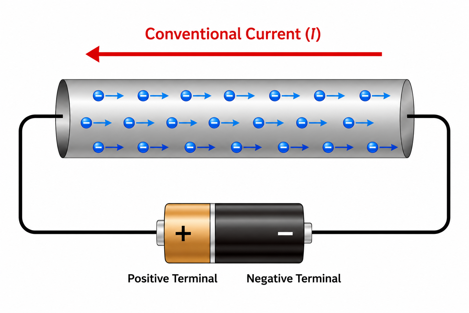
Direction of Current: By convention, the direction of current is taken as the direction of flow of positive charges. Therefore, the conventional current flows from higher potential to lower potential, which is exactly opposite to the direction of flow of electrons.
Charge Carriers in Different Media:
- Solid Conductors: Free electrons.
- Liquids (Electrolytes): Positive and negative ions.
- Gases: Positive ions and free electrons (gases conduct only at low pressure and high potential difference).
2. Ohm's Law, Resistance, and Resistivity
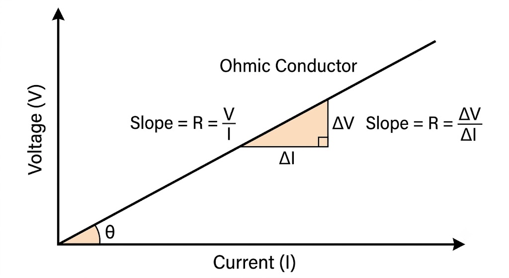
Ohm's Law: The physical state (temperature, mechanical strain, etc.) remaining unchanged, the current flowing through a conductor is directly proportional to the potential difference across its ends.
$$V \propto I \implies \mathbf{V = IR}$$
Where $R$ is the constant of proportionality known as Electrical Resistance. Its SI unit is the Ohm ($\Omega$). Resistance is the opposition offered by the substance to the flow of electric current, caused by the collision of moving electrons with fixed positive ions/atoms.
Factors Affecting Resistance
Resistance of a conductor depends directly on its length ($l$) and inversely on its cross-sectional area ($A$):
$$R = \rho \frac{l}{A}$$
Where $\rho$ (rho) is the Resistivity (or Specific Resistance) of the material. Resistivity depends only on the nature of the material and its temperature, NOT on its shape or size! Its SI unit is $\Omega\cdot\text{m}$.
Conductance ($G$) & Conductivity ($\sigma$):
Conductance is the reciprocal of resistance: $G = \frac{1}{R}$ (Unit: Siemens or Mho or $\Omega^{-1}$).
Conductivity is the reciprocal of resistivity: $\sigma = \frac{1}{\rho}$ (Unit: $S/m$ or $\Omega^{-1}m^{-1}$).
Vector Form of Ohm's Law (Important Board Derivation)
Current Density ($\vec{J}$): The current flowing per unit area perpendicular to the direction of current. $J = \frac{I}{A}$. It is a Vector quantity. Unit: $A/m^2$.
Derivation: $\vec{J} = \sigma \vec{E}$
Consider a conductor of length $l$ and area $A$. Let $V$ be the potential difference across it.
Electric field $E = \frac{V}{l} \implies V = El$
By Ohm's Law: $V = IR$
Substitute $R = \rho \frac{l}{A}$:
$V = I \left( \rho \frac{l}{A} \right)$
Equating the two expressions for V:
$El = I \rho \frac{l}{A}$
$E = \left( \frac{I}{A} \right) \rho$
Since $J = I/A$, we get $E = J \rho$.
Rearranging: $J = \frac{1}{\rho} E$
Since $\sigma = 1/\rho$, we get the vector form: $\vec{J} = \sigma \vec{E}$
JEE Main Transition: Stretching of Wires
If a wire is stretched, its volume ($V = A \times l$) remains constant. If length is increased $n$ times ($l' = nl$), the area must decrease by $n$ times ($A' = A/n$).
New Resistance: $R' = \rho \frac{l'}{A'} = \rho \frac{nl}{A/n} = n^2 \left( \rho \frac{l}{A} \right) = \mathbf{n^2 R}$
Rule: If length is stretched $n$ times, resistance increases $n^2$ times!
3. Drift Velocity and Origin of Resistivity (Crucial for Boards)
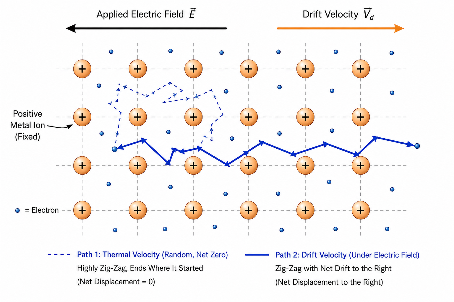
In a normal room-temperature conductor without a battery, free electrons move randomly with huge Thermal Velocities ($\approx 10^5 \text{ m/s}$). Because this motion is completely random, the average thermal velocity of all electrons is zero ($\vec{u}_{avg} = 0$), so there is no net current.
Drift Velocity ($\vec{v}_d$): When an electric field is applied, the free electrons experience a force and slowly "drift" towards the positive terminal superimposed on their random thermal motion. It is very small ($\approx 10^{-4} \text{ m/s}$).
Relaxation Time ($\tau$): The average time interval between two successive collisions of an electron with the positive ions. If temperature increases, electrons move faster, collisions happen more frequently, and $\tau$ decreases.
Derivation 1: Drift Velocity
Force on an electron: $\vec{F} = -e\vec{E}$
Acceleration: $\vec{a} = \frac{\vec{F}}{m} = -\frac{e\vec{E}}{m}$
Using $v = u + at$ (average over all electrons):
$\vec{v}_d = \vec{u}_{avg} + \vec{a}\tau$
Since $\vec{u}_{avg} = 0$:
$$\vec{v}_d = -\frac{e\vec{E}}{m}\tau$$
Derivation 2: Relation between I and $v_d$ (Extremely Important)
Consider a conductor of length $l$ and area $A$. Let $n$ be the number density of electrons (electrons per unit volume).
Volume of conductor = $Al$
Total number of free electrons = $nAl$
Total charge $q = (nAl)e$
Time taken for electrons to cross the conductor $t = \frac{l}{v_d}$
Current $I = \frac{q}{t} = \frac{nAle}{l/v_d}$
$$I = neAv_d$$
Derivation 3: Deduction of Ohm's Law
From $I = neAv_d$, substitute $v_d = \frac{eE\tau}{m}$ (magnitude only):
$I = neA \left( \frac{eE\tau}{m} \right) = \frac{ne^2A\tau}{m} E$
Substitute $E = \frac{V}{l}$:
$I = \frac{ne^2A\tau}{m} \frac{V}{l}$
Rearranging for V:
$V = \left( \frac{m}{ne^2\tau} \frac{l}{A} \right) I$
Comparing with $V = IR$, we get:
$$R = \frac{m}{ne^2\tau} \frac{l}{A} \quad \text{and} \quad \rho = \frac{m}{ne^2\tau}$$
Mobility ($\mu$): Defined as the magnitude of drift velocity per unit electric field.
$$\mu = \frac{v_d}{E} = \frac{e\tau}{m}$$
SI Unit: $m^2/V\cdot s$. Mobility is always positive.
4. Limitations of Ohm's Law (Non-Ohmic Devices)
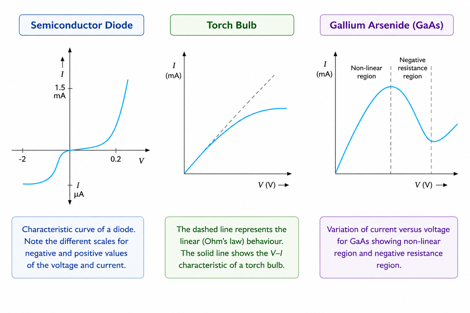
Materials and devices that do not obey Ohm's Law ($V = IR$) are called non-ohmic. Their deviations manifest in three ways:
- Non-linear relation: $V$ ceases to be proportional to $I$ (e.g., heating of a filament bulb changes its resistance).
- Asymmetry: The relation between $V$ and $I$ depends on the sign of $V$. Reversing the voltage direction drastically changes the current magnitude (e.g., Semiconductor P-N junction diode).
- Non-unique relation: The same current $I$ can exist for more than one value of voltage $V$ (e.g., Gallium Arsenide - GaAs, which exhibits a negative resistance region).
5. Temperature Dependence of Resistivity
The resistivity of materials changes with temperature according to the relation:
$$\rho_T = \rho_0 [1 + \alpha(T - T_0)] \quad \text{and} \quad R_T = R_0 [1 + \alpha(T - T_0)]$$
Where $\alpha$ is the Temperature Coefficient of Resistivity. Its unit is $^\circ C^{-1}$ or $K^{-1}$.
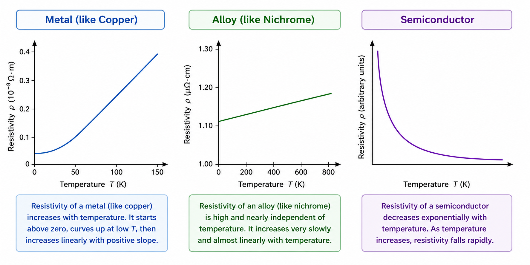
- Metals (Conductors): $\alpha$ is positive. As T increases, relaxation time $\tau$ decreases (ions vibrate more vigorously, causing more collisions), so resistivity $\rho$ increases.
- Alloys (e.g., Nichrome, Manganin): $\alpha$ is very small and positive. Their resistance is almost independent of temperature, which is why they are used to make standard wire-wound resistors.
- Semiconductors and Insulators: $\alpha$ is negative! As T increases, many covalent bonds break, exponentially increasing the number density of charge carriers ($n$). This completely dominates the decrease in $\tau$, so overall resistivity decreases ($\rho \propto e^{E_g/kT}$).
6. Carbon Resistors and Color Coding (Important for NEET)
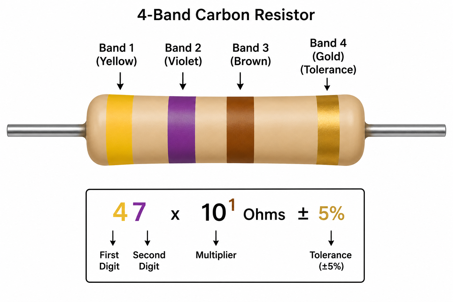
Commercial resistors are mostly made of carbon because they are compact and inexpensive. Their values are indicated by a color code.
Color Code Mnemonic
B B R O Y of Great Britain has a Very Good Wife.
(Black=0, Brown=1, Red=2, Orange=3, Yellow=4, Green=5, Blue=6, Violet=7, Gray=8, White=9).
How to read:
1st and 2nd bands: First two significant figures.
3rd band: Decimal multiplier ($10^x$).
4th band: Tolerance (Gold = $\pm 5\%$, Silver = $\pm 10\%$, No color = $\pm 20\%$).
7. Electrical Energy and Power
The rate at which electrical energy is dissipated (or consumed) is electrical power.
$$P = VI = I^2R = \frac{V^2}{R}$$
Joule's Law of Heating: Heat produced $H = I^2Rt$ (Energy = Power $\times$ Time).
Bulb Brightness Rules
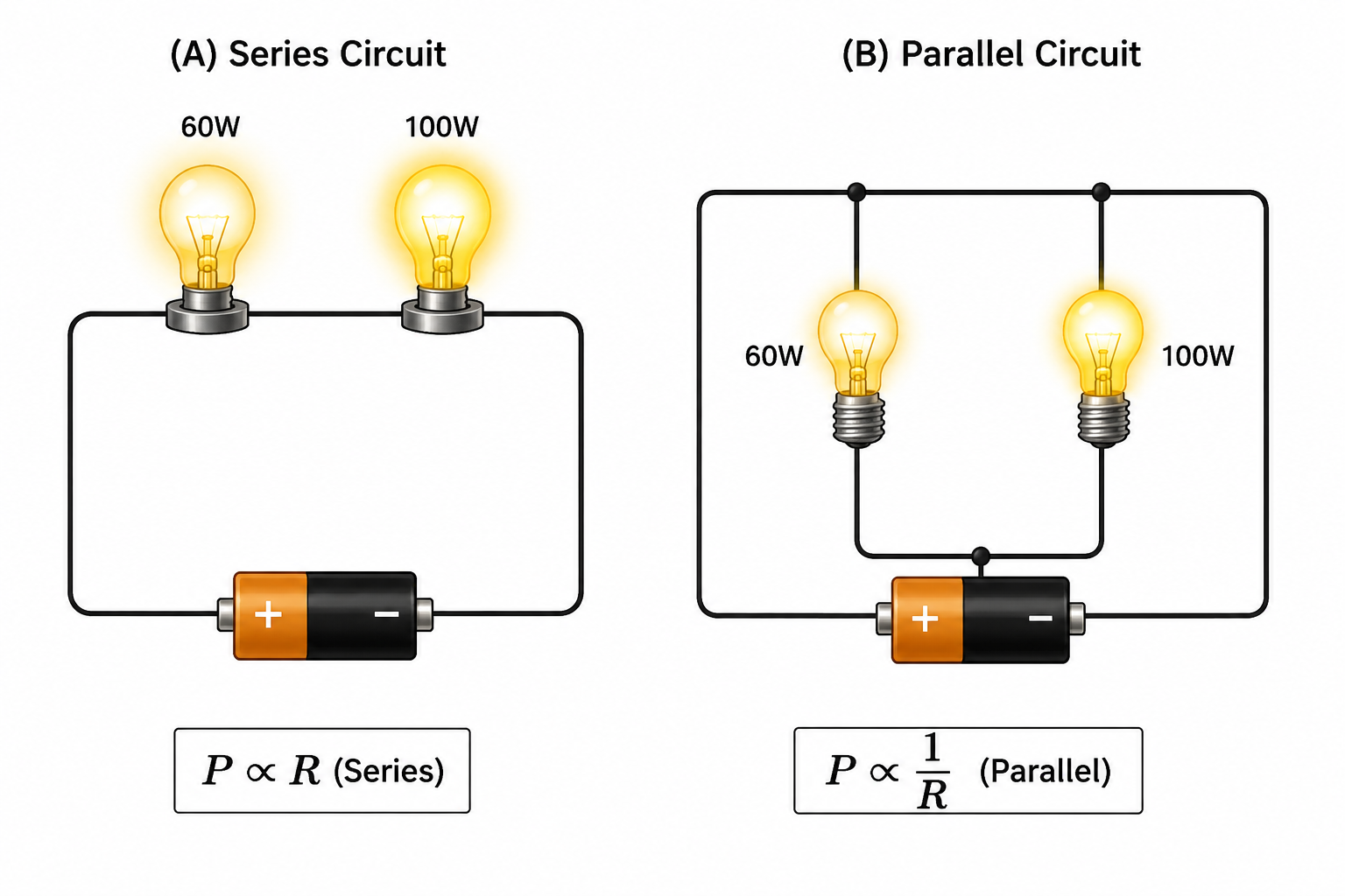
The resistance of a bulb is determined by its rating: $R = \frac{V_{rated}^2}{P_{rated}}$. A 100W bulb has less resistance than a 60W bulb.
- In Series: Current ($I$) is constant. Power dissipated is $P = I^2R$. Hence, $P \propto R$. The bulb with higher resistance (the 60W bulb) glows brighter!
- In Parallel: Voltage ($V$) is constant. Power dissipated is $P = V^2/R$. Hence, $P \propto 1/R$. The bulb with lower resistance (the 100W bulb) glows brighter!
8. Combination of Resistors
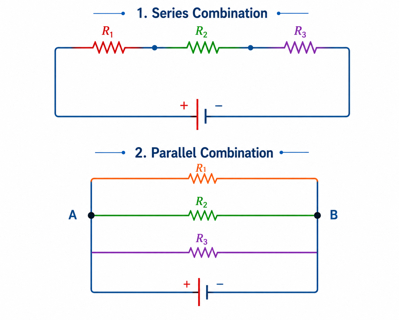
A. Series Combination
Current is the same through all resistors. Voltage is divided ($V = V_1 + V_2 + V_3$).
$$R_{eq} = R_1 + R_2 + R_3 + \dots + R_n$$
(Equivalent resistance is always greater than the largest individual resistance in the series combination.)
B. Parallel Combination
Voltage is the same across all resistors. Current is divided ($I = I_1 + I_2 + I_3$).
$$\frac{1}{R_{eq}} = \frac{1}{R_1} + \frac{1}{R_2} + \frac{1}{R_3} + \dots + \frac{1}{R_n}$$
Shortcut Formulas
- For two resistors in parallel: $R_{eq} = \frac{R_1 R_2}{R_1 + R_2}$
- For $n$ identical resistors in parallel: $R_{eq} = \frac{R}{n}$
(Equivalent resistance is always less than the smallest individual resistance in the parallel combination.)
9. Cells, EMF, and Internal Resistance
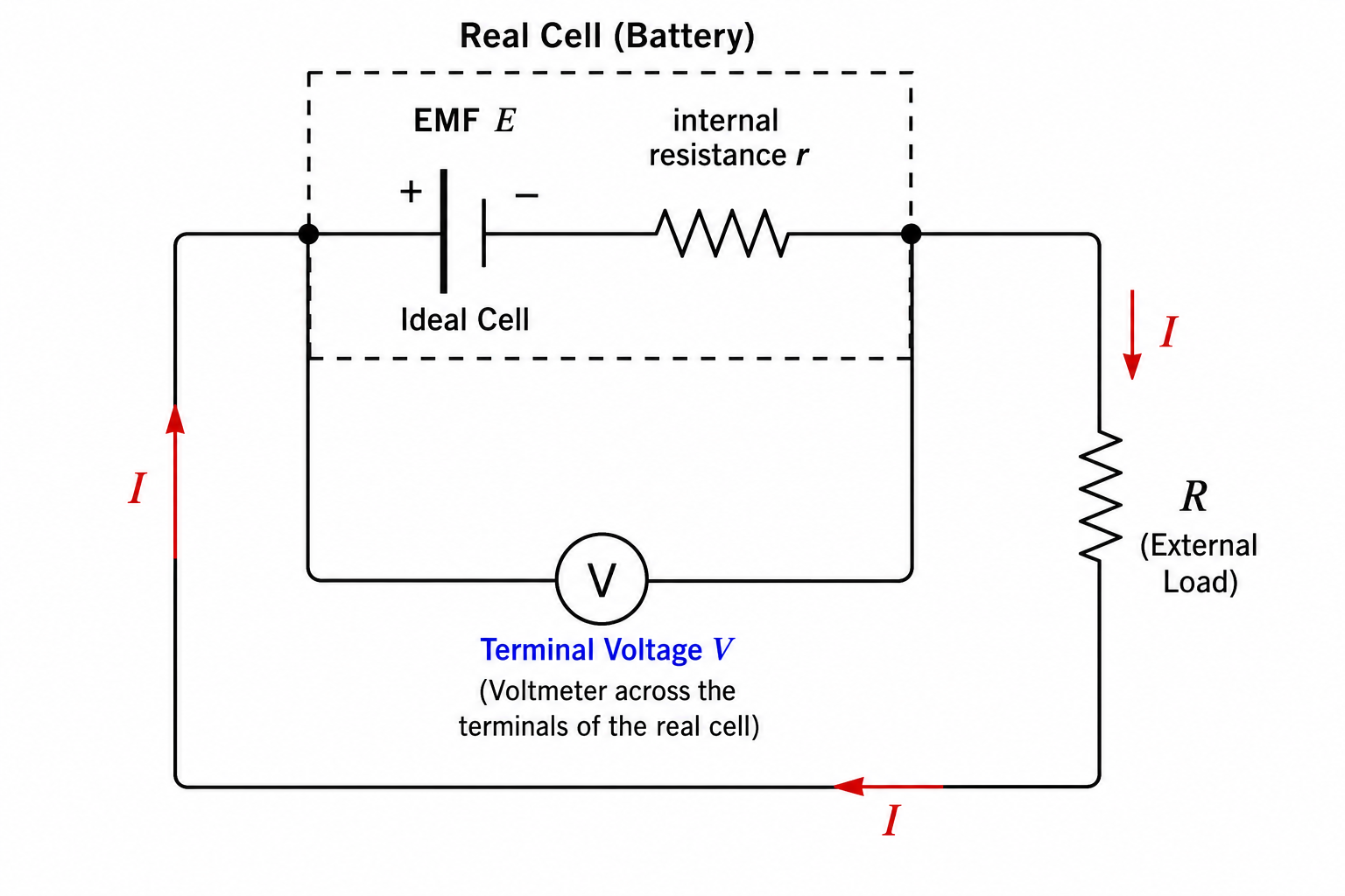
- Electromotive Force (EMF, $E$): The maximum potential difference between the two electrodes of a cell when no current is drawn from it (open circuit). It is the work done by the chemical forces to move a unit positive charge from the lower potential to higher potential inside the cell.
- Internal Resistance ($r$): The finite resistance offered by the electrolyte and electrodes of a cell to the flow of current.
- Terminal Potential Difference ($V$): The potential difference across the terminals of a cell when current is being drawn from it.
Equations of a Cell
- Discharging (Current drawn from cell): $V = E - Ir$. (Here $V < E$).
- Charging (Current forced into cell): $V = E + Ir$. (Here $V > E$).
- Open Circuit (No current): $I = 0 \implies V = E$.
Current in the circuit: $I = \frac{E}{R + r}$.
10. Combination of Cells
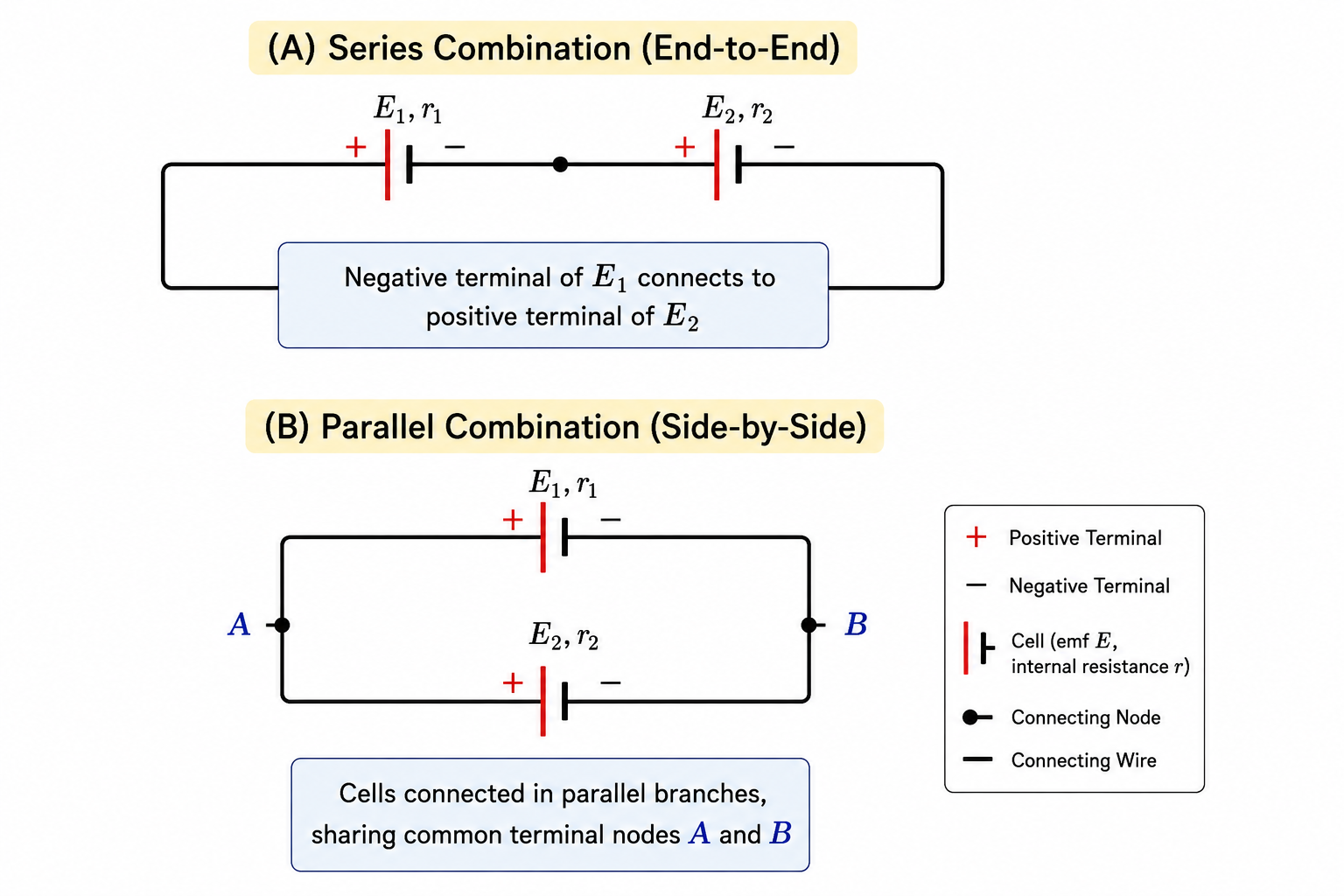
A. Cells in Series
If $n$ cells are connected in series (supporting each other):
- Equivalent EMF: $E_{eq} = E_1 + E_2 + \dots + E_n$
- Equivalent Internal Resistance: $r_{eq} = r_1 + r_2 + \dots + r_n$
B. Cells in Parallel
For two cells of EMFs $E_1, E_2$ and internal resistances $r_1, r_2$ connected in parallel:
Parallel Formulas
Equivalent EMF: $$E_{eq} = \frac{E_1 r_2 + E_2 r_1}{r_1 + r_2}$$
Equivalent Internal Resistance: $$\frac{1}{r_{eq}} = \frac{1}{r_1} + \frac{1}{r_2} \implies r_{eq} = \frac{r_1 r_2}{r_1 + r_2}$$
11. Kirchhoff's Rules (Highly Important for Numericals)
When circuits cannot be reduced to simple series and parallel combinations, we use Kirchhoff's Rules.
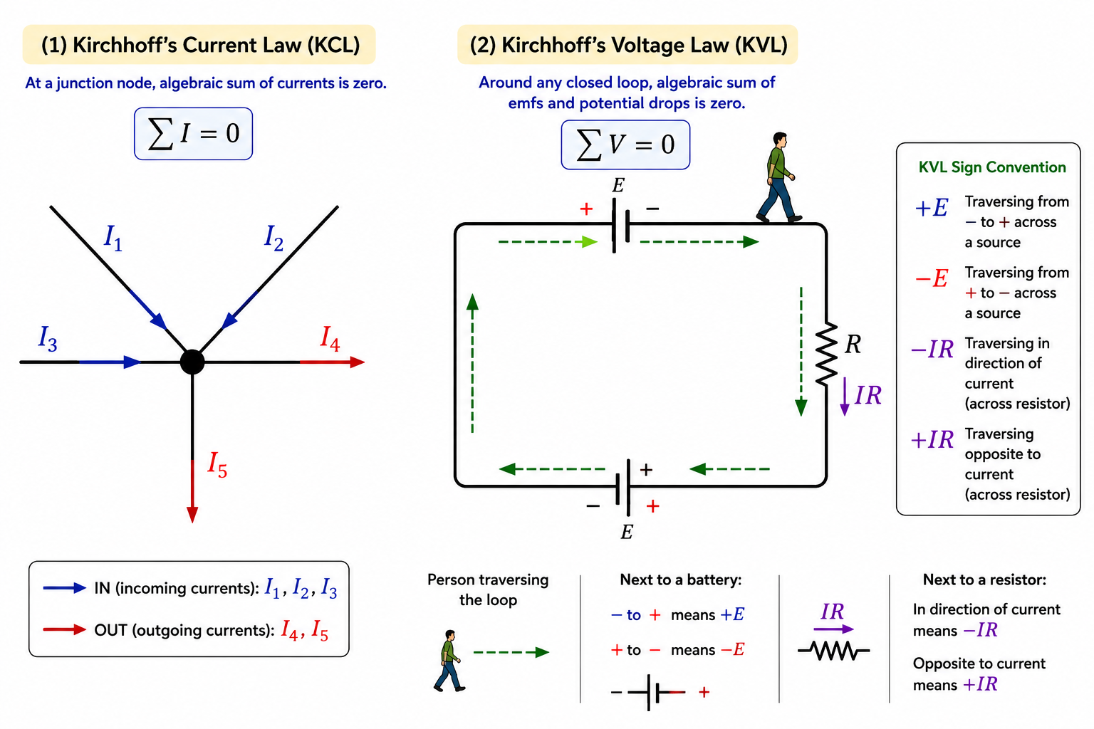
1. Kirchhoff's First Rule (Junction Rule / KCL)
"The algebraic sum of currents meeting at a junction in a closed circuit is zero." $\sum I = 0$
Sum of currents entering a junction = Sum of currents leaving it.
Principle: Based on the Law of Conservation of Charge.
2. Kirchhoff's Second Rule (Loop Rule / KVL)
"The algebraic sum of changes in potential around any closed loop involving resistors and cells in the loop is zero." $\sum \Delta V = 0$
Principle: Based on the Law of Conservation of Energy.
Sign Convention for KVL Loop Traversal
- Batteries: If you traverse through a battery from Negative to Positive, EMF is positive ($+E$). If from Positive to Negative, EMF is negative ($-E$).
- Resistors: If you traverse through a resistor in the same direction as the assumed current, the potential drops ($-IR$). If you traverse in the opposite direction to the current, the potential rises ($+IR$).
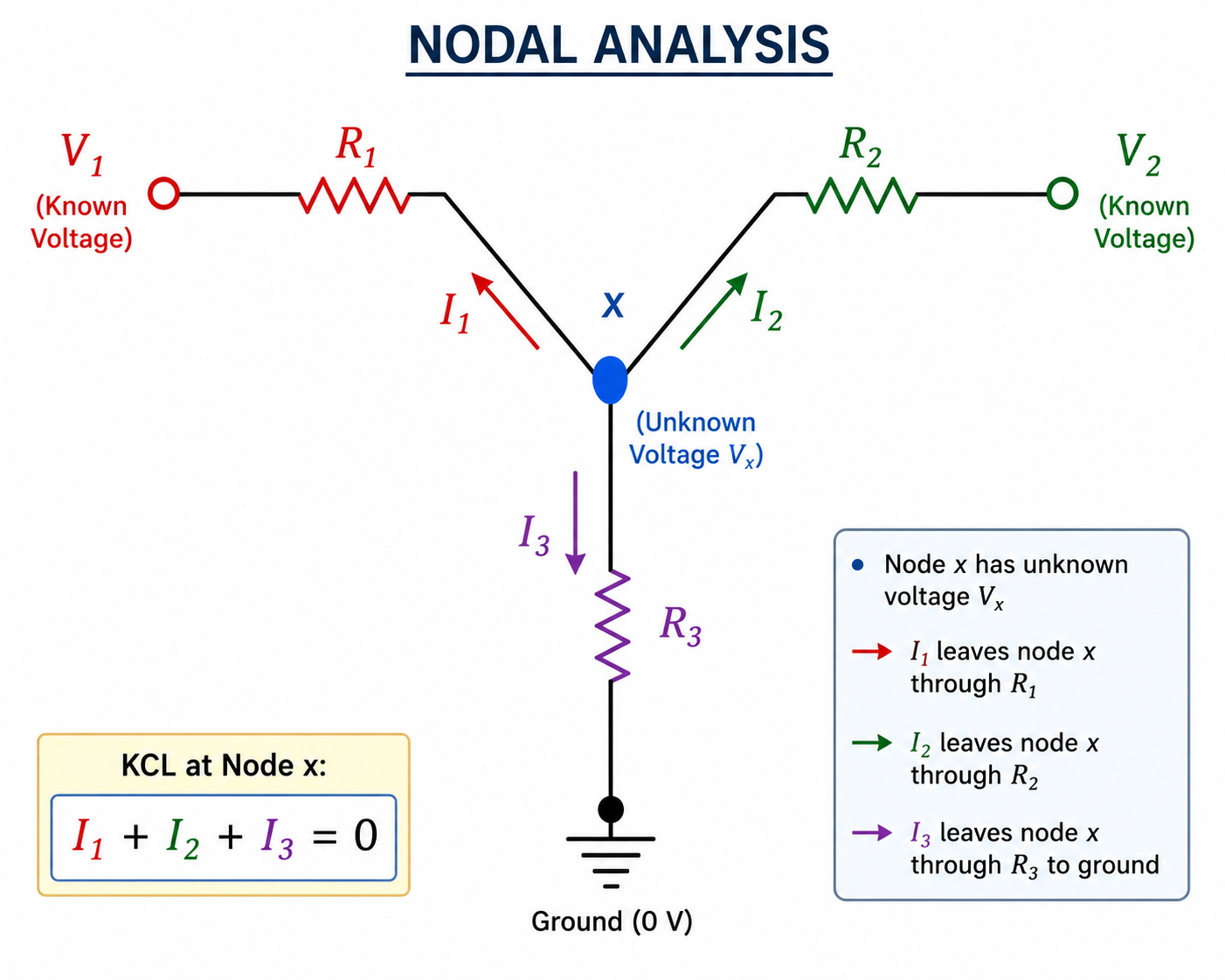
JEE Pro-Tip: Nodal Analysis
Nodal Analysis is a powerful shortcut to solve complex circuits much faster than Kirchhoff's rules by applying KCL at a junction in terms of node voltages.
Steps:
- Identify the principal nodes (junctions where 3 or more branches meet).
- Assign one node as the "reference node" (Ground) and set its potential to $0\text{V}$.
- Assign unknown potentials (e.g., $x, y$) to the other principal nodes.
- Assume current flows out of the unknown node into all branches. Apply KCL: $\sum I_{out} = 0$.
- Write currents as $I = \frac{\Delta V}{R}$ (e.g., $\frac{x - V_{adjacent}}{R}$). Solve for $x$.
Once you know the node voltages, you can find the current through any branch instantly!
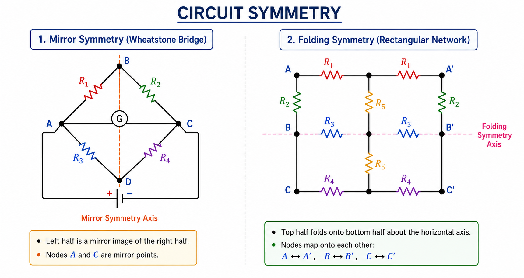
JEE Pro-Tip: Circuit Symmetry
For complex infinite or 3D grids (like a cube of resistors), use symmetry to eliminate branches.
- Mirror Symmetry: If a circuit is symmetric about an axis perpendicular to the current flow, nodes on this axis are at the same potential. Resistors crossing this axis carry zero current and can be removed.
- Folding Symmetry: If a circuit is symmetric about an axis parallel to the current flow, nodes opposite each other on the axis are at the same potential and can be folded (merged).
12. Wheatstone Bridge
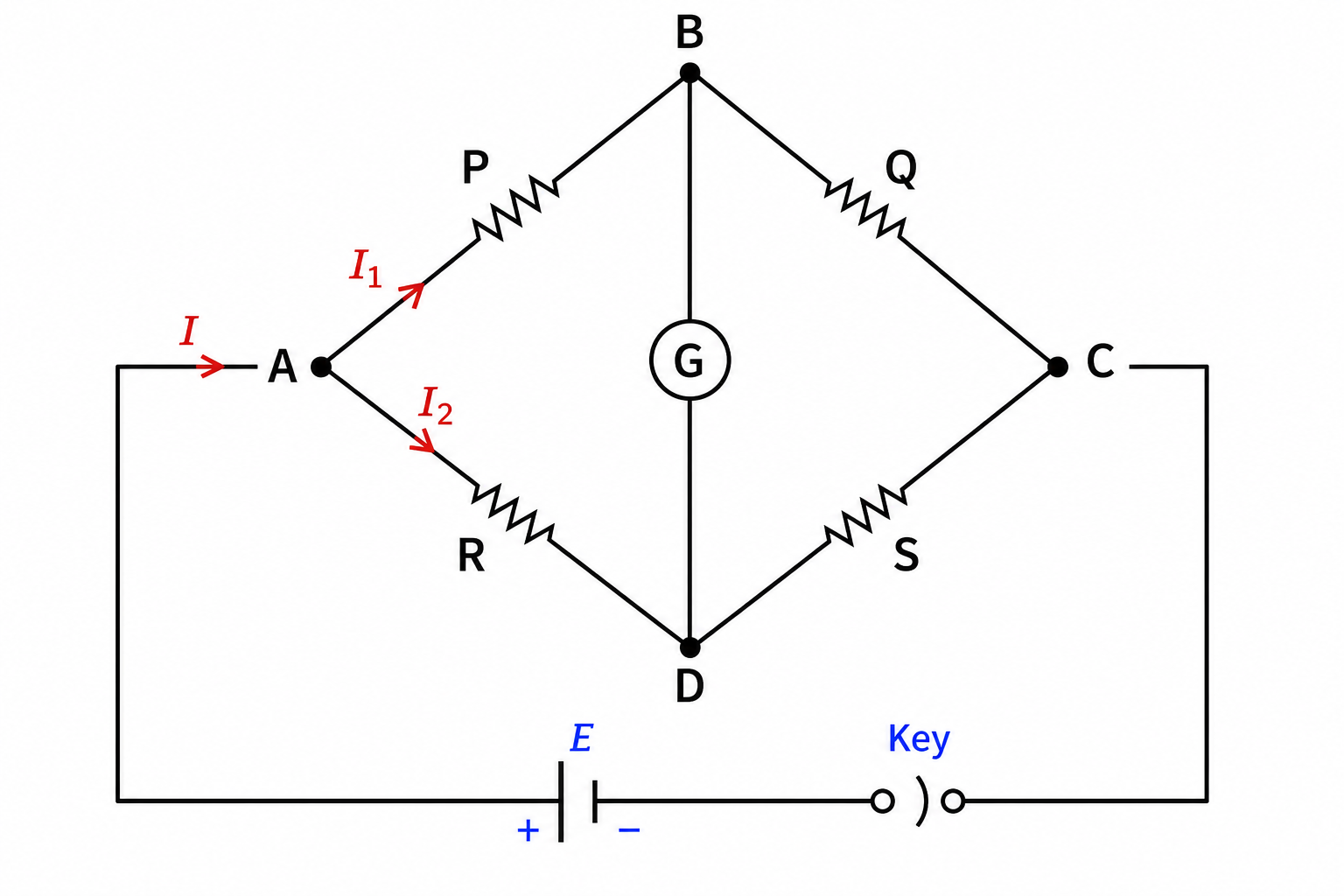
A Wheatstone bridge is an arrangement of four resistances $P, Q, R, S$ used to determine an unknown resistance accurately.
Balanced Condition
The bridge is said to be balanced if no current flows through the galvanometer ($I_g = 0$). This happens when the potential at nodes B and D are exactly equal ($V_B = V_D$).
Balanced Formula
$$\frac{P}{Q} = \frac{R}{S}$$
(When balanced, you can completely ignore/remove the galvanometer branch from your circuit calculations!)
13. Measuring Instruments (JEE Main Focus)
Note: Meter bridge and Potentiometer are heavily tested in JEE Mains, especially in error analysis and practical physics.
A. Galvanometer to Ammeter
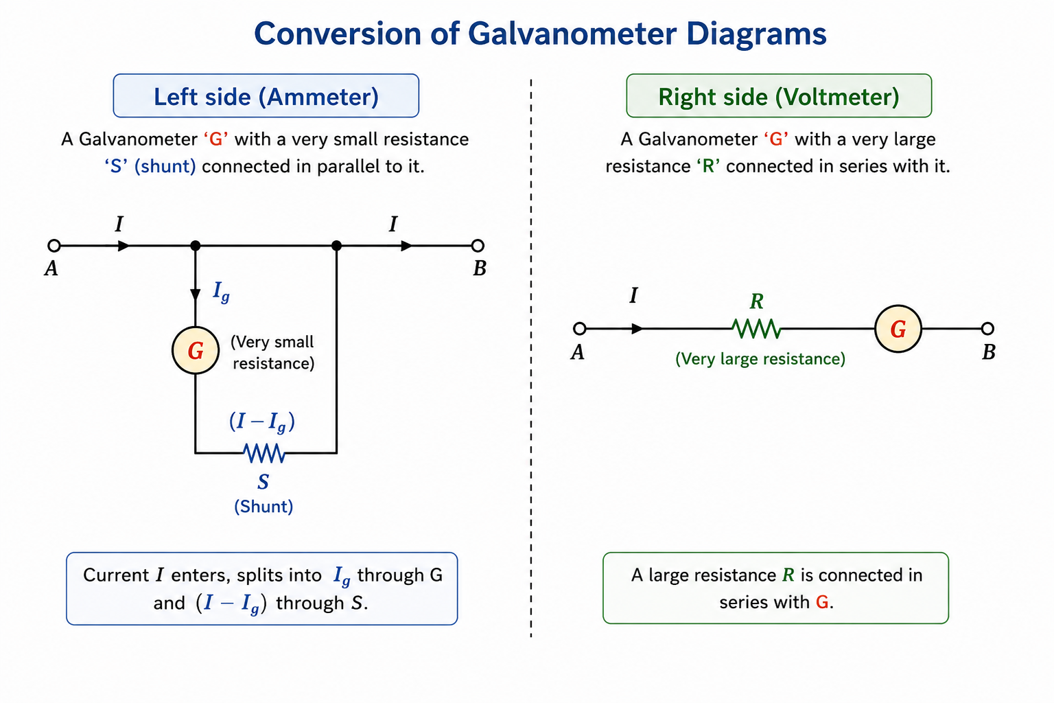
A galvanometer is converted into an ammeter (which measures current) by connecting a very small resistance called a Shunt ($S$) in parallel to it. The ammeter is then placed in series in the main circuit.
$$S = \frac{I_g \times G}{I - I_g}$$
Where $I_g$ is the full-scale deflection current of the galvanometer, and $I$ is the total range to be measured.
B. Galvanometer to Voltmeter
A galvanometer is converted into a voltmeter (which measures potential difference) by connecting a very high resistance ($R$) in series with it. The voltmeter is then placed in parallel across the component.
$$R = \frac{V}{I_g} - G$$
C. Potentiometer (Principle)
It measures potential difference without drawing any current from the voltage source (acts as an ideal voltmeter). Principle: The potential drop across any length of a wire of uniform cross-section is directly proportional to that length ($V \propto l$).
- Comparing EMFs: $\frac{E_1}{E_2} = \frac{l_1}{l_2}$
- Finding Internal Resistance: $r = R \left( \frac{l_1}{l_2} - 1 \right)$
D. Meter Bridge (Slide Wire Bridge)
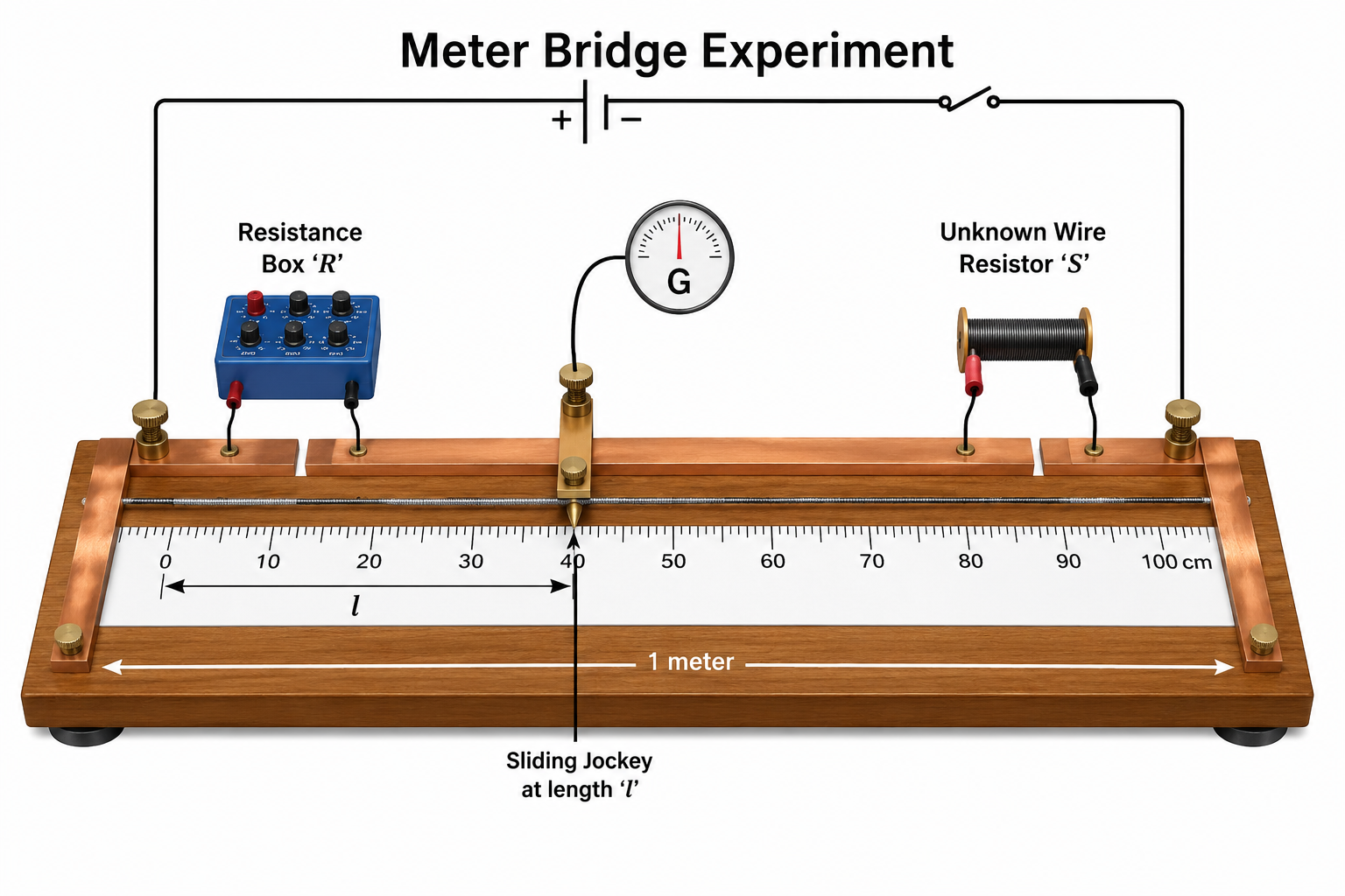
A meter bridge is the practical application of the Wheatstone bridge principle, used to find an unknown resistance.
When the jockey is slid over the 1-meter long wire (made of manganin or constantan) to a point where the galvanometer shows zero deflection (null point), the bridge is balanced.
Meter Bridge Formula
Let the balancing length from the left end be $l$ cm. The resistance of the wire is proportional to its length.
Using Wheatstone condition: $\frac{R}{S} = \frac{l}{100-l}$
$$S = R \left( \frac{100-l}{l} \right)$$
JEE Focus: End Corrections
In a real meter bridge, the copper strips at the ends and the solder joints offer some small resistance. These are called End Resistances (let them be equivalent to lengths $\alpha$ and $\beta$ of the wire). The modified formula becomes:
$$\frac{R}{S} = \frac{l + \alpha}{100 - l + \beta}$$