
Class 10 Science • Chapter 12 (Deep Detail)
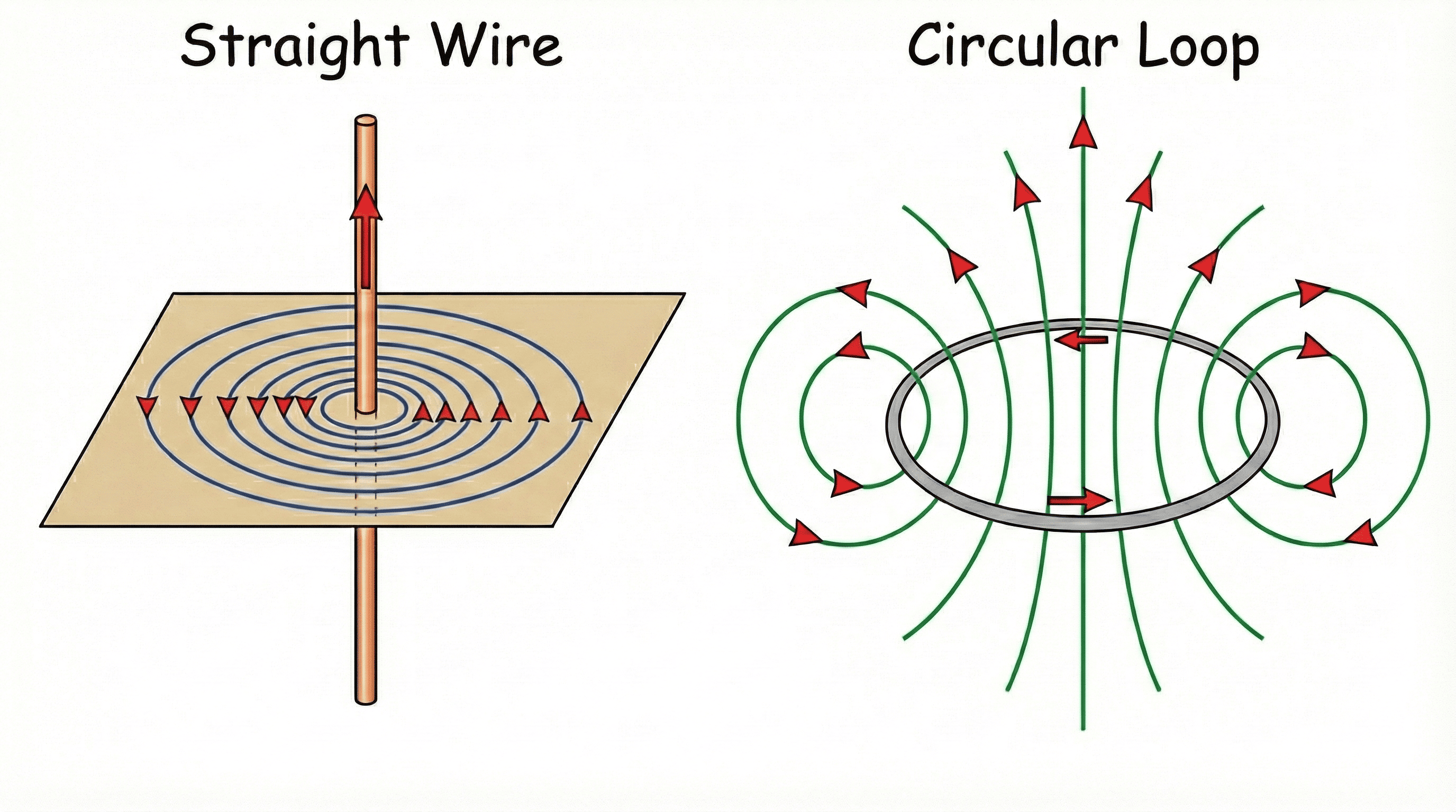 Figure 4.1: Magnetic Field — Straight Current-Carrying Wire (left) & Circular Loop
(right)
Figure 4.1: Magnetic Field — Straight Current-Carrying Wire (left) & Circular Loop
(right)
When electric current flows through a conductor, it produces a magnetic field around it. This was first demonstrated by Hans Christian Ørsted in 1820.
Imagine holding the current-carrying straight conductor in your right hand such that your thumb points in the direction of the current. Then your fingers will wrap around the conductor in the direction of the magnetic field lines.
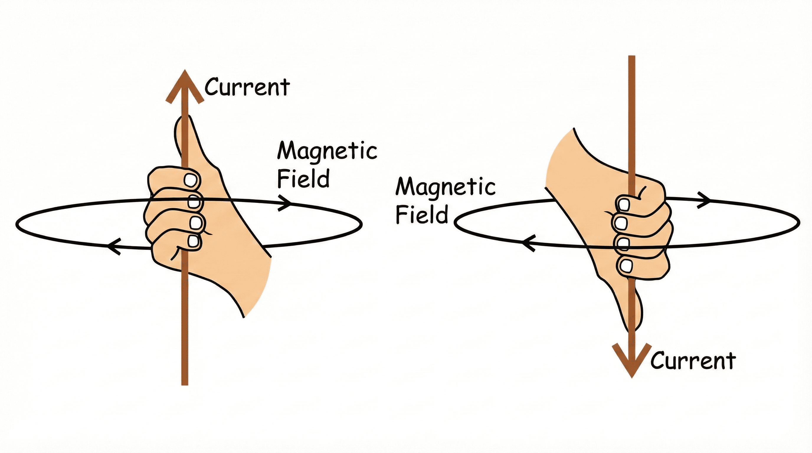 Figure 4.2: Right-Hand Thumb Rule — Thumb points along current, fingers curl in
direction of magnetic field.
Figure 4.2: Right-Hand Thumb Rule — Thumb points along current, fingers curl in
direction of magnetic field.
The magnetic field lines are concentric circles near the wire, becoming straighter as they move away. At the center of the loop, the field lines are almost straight and perpendicular to the plane of the loop.
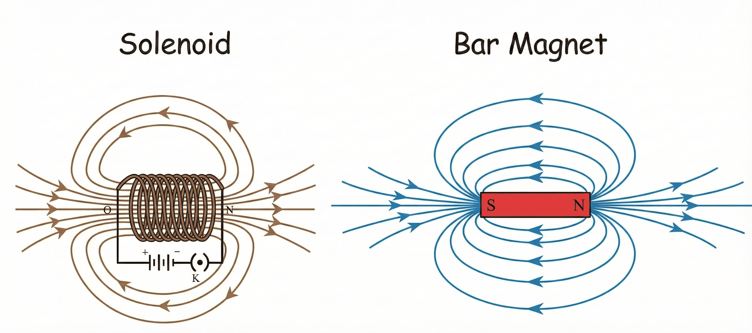 Figure 4.3: Bar Magnet (top) vs Solenoid (bottom) — both produce similar field
patterns.
Figure 4.3: Bar Magnet (top) vs Solenoid (bottom) — both produce similar field
patterns.
A solenoid is a coil of many circular turns of insulated copper wire wrapped closely in the shape of a cylinder. The magnetic field produced by a solenoid is similar to that of a bar magnet.
| Property | Electromagnet | Permanent Magnet |
|---|---|---|
| Nature of Magnetism | Temporary (exists only when current flows). | Permanent. |
| Strength | Can be varied by changing current or number of turns. | Fixed strength. |
| Polarity | Can be reversed by reversing current direction. | Fixed polarity. |
| Demagnetization | Easily demagnetized by switching off current. | Cannot be easily demagnetized. |
| Material | Soft iron core. | Steel, Alnico, Neodymium. |
| Applications | Electric bells, cranes, motors, generators. | Refrigerators, compasses, loudspeakers. |
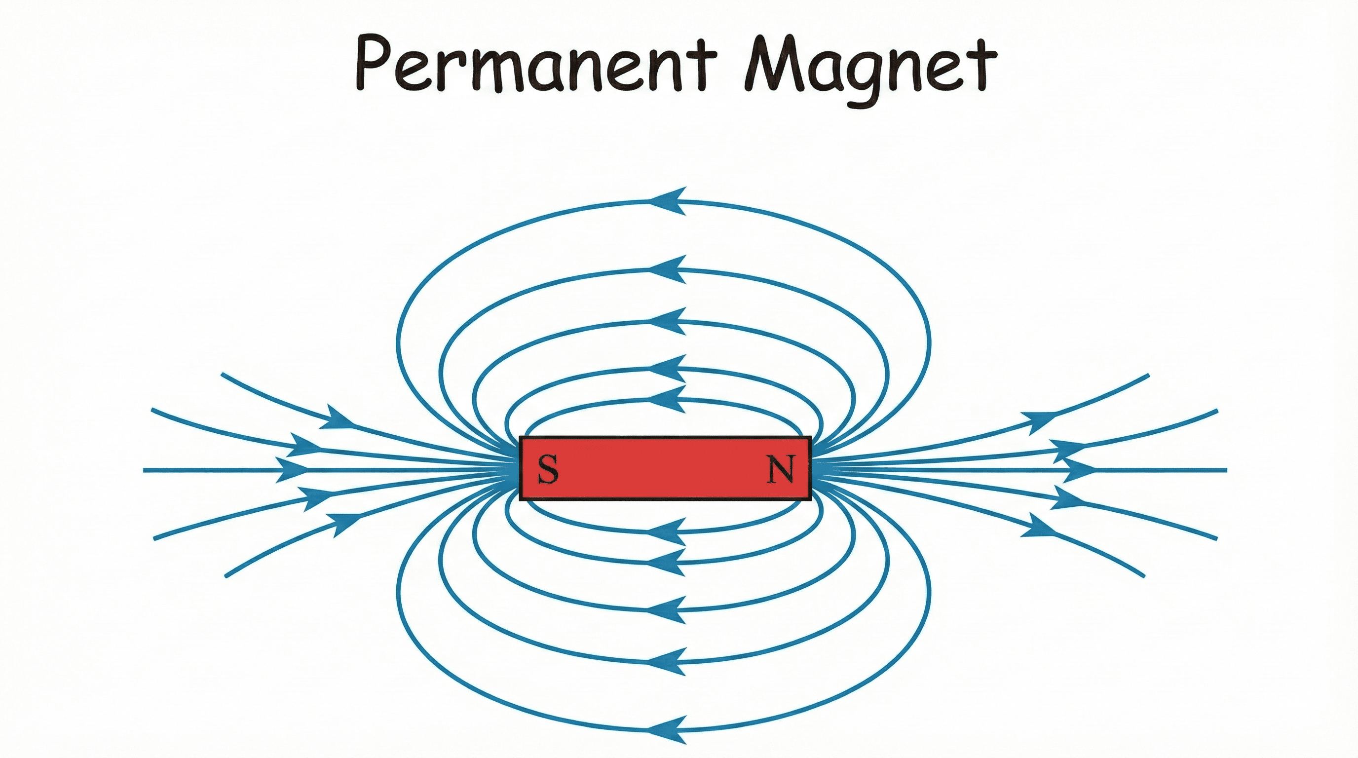 Figure 4.6: Permanent Magnet — Horseshoe and Bar type magnets showing field line
patterns
Figure 4.6: Permanent Magnet — Horseshoe and Bar type magnets showing field line
patterns
A current-carrying conductor placed in a magnetic field experiences a force. This is known as the Motor Effect. The direction of this force is given by Fleming's Left-Hand Rule.
Stretch the thumb, forefinger, and middle finger of your left hand such that they are mutually perpendicular to each other.
A common mnemonic: Father (Force) - Mother (Magnetic Field) - Child (Current).
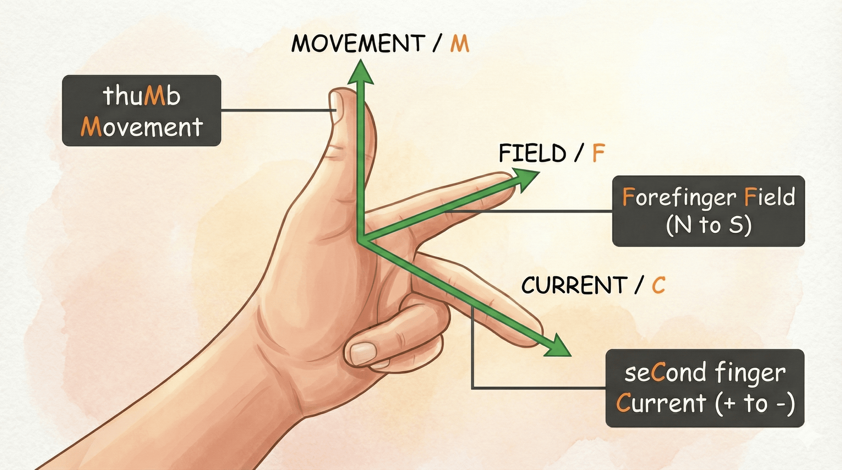 Figure 4.4: Fleming's Left-Hand Rule — Forefinger = B (Field), Middle Finger = I
(Current), Thumb = F (Force).
Figure 4.4: Fleming's Left-Hand Rule — Forefinger = B (Field), Middle Finger = I
(Current), Thumb = F (Force).
| Property | Electric Motor | Electric Generator |
|---|---|---|
| Principle | Motor Effect (Force on current-carrying conductor in B-field). | Electromagnetic Induction (Producing current by changing B-field). |
| Energy Conversion | Electrical energy to Mechanical energy. | Mechanical energy to Electrical energy. |
| Input | Electric current. | Mechanical rotation. |
| Output | Rotation/Motion. | Electric current. |
| Rule Used | Fleming's Left-Hand Rule. | Fleming's Right-Hand Rule. |
| Key Component | Split ring commutator (for DC motor). | Slip rings (for AC generator) or Split ring (for DC generator). |
Electricity is supplied to our homes through a main supply (mains) either from a pole or underground cables. The main wires are:
All appliances in a domestic circuit are connected in parallel to ensure they receive the same voltage and can be operated independently.
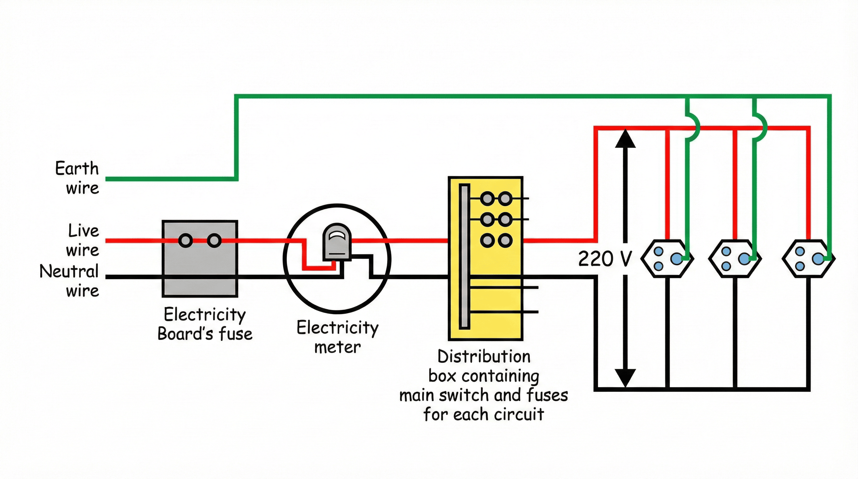 Figure 4.5: Domestic Electric Circuit — Meter Board, Distribution Box, Parallel
branches for appliances.
Figure 4.5: Domestic Electric Circuit — Meter Board, Distribution Box, Parallel
branches for appliances.
The earth wire provides a low-resistance path for current. It is connected to the metallic body of appliances (like electric iron, toaster, refrigerator).
| Property | Alternating Current (AC) | Direct Current (DC) |
|---|---|---|
| Direction | Reverses periodically. | Flows in one constant direction. |
| Magnitude | Varies with time. | Constant (or nearly constant). |
| Source | AC generators, power plants. | Batteries, cells, DC generators, solar cells. |
| Transmission | Can be transmitted over long distances without significant energy loss (using transformers). | Cannot be transmitted over long distances without significant energy loss. |
| Frequency | 50 Hz (India), 60 Hz (USA). | 0 Hz. |
| Applications | Household electricity, industrial power. | Electronic devices, charging batteries, electroplating. |