
Board Exam 2025
1 Mark
Q14. Which one of the following factors
affects the electrical resistivity of a conductor ?
Resistivity (\(\rho\)) is a material property. It depends only on the
nature of the material and temperature.
Resistance (R) depends on length and area (thickness/shape), but Resistivity does not.
Correct Option: (A)
Resistance (R) depends on length and area (thickness/shape), but Resistivity does not.
Correct Option: (A)
3 Marks
Q31. (a) Write mathematical expression for
Joule�s law of heating.
(b) Calculate the amount of heat generated while transferring 72000 coulomb of charge in two hours through a potential difference of 220 V.
(b) Calculate the amount of heat generated while transferring 72000 coulomb of charge in two hours through a potential difference of 220 V.
(a) Joule's Law: \(H = I^2Rt\) or \(H = VIt\).
Where H = Heat, I = Current, R = Resistance, t = Time.
(b) Calculation:
Charge \(Q = 72000\text{ C}\).
Voltage \(V = 220\text{ V}\).
Formula: Work (Heat) \(W = V \times Q\).
\(H = 220 \times 72000\)
\(H = 1,58,40,000\text{ J}\)
Heat = 1.584 × 10\(^7\) J
Where H = Heat, I = Current, R = Resistance, t = Time.
(b) Calculation:
Charge \(Q = 72000\text{ C}\).
Voltage \(V = 220\text{ V}\).
Formula: Work (Heat) \(W = V \times Q\).
\(H = 220 \times 72000\)
\(H = 1,58,40,000\text{ J}\)
Heat = 1.584 × 10\(^7\) J
4 Marks
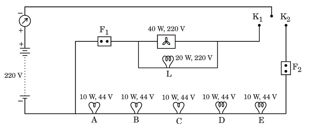
Q38. In a domestic circuit, six LED bulbs and a
ceiling fan are arranged as per the circuit shown in the figure. [See Image]
 38.png"
class="question-image" alt="2025-31-S-QuestionNumber38.png" style="max-width: 80%; max-height: 60vh;
object-fit: contain; height: auto; display: block; margin: 10px auto; border-radius: 8px;">
38.png"
class="question-image" alt="2025-31-S-QuestionNumber38.png" style="max-width: 80%; max-height: 60vh;
object-fit: contain; height: auto; display: block; margin: 10px auto; border-radius: 8px;">
(a) State what happens when:
(i) only key \(K_1\) is closed,
(ii) and key \(K_2\) is also closed.
(b) Find the current drawn by the bulb L.
(c) (i) Calculate the resistance of the bulb A. Find the total resistance offered by the circuit to the flow of current when only key \(K_2\) is closed.
OR
(c) (ii) What would happen to the glow of the bulbs in the circuit when \(K_1\) and \(K_2\) both are closed and the fuse \(F_1\) melts suddenly? Give reason to justify your answer. The circuit is connected across 220V.
38.png"
class="question-image" alt="2025-31-S-QuestionNumber38.png" style="max-width: 80%; max-height: 60vh;
object-fit: contain; height: auto; display: block; margin: 10px auto; border-radius: 8px;">
(a) State what happens when:
(i) only key \(K_1\) is closed,
(ii) and key \(K_2\) is also closed.
(b) Find the current drawn by the bulb L.
(c) (i) Calculate the resistance of the bulb A. Find the total resistance offered by the circuit to the flow of current when only key \(K_2\) is closed.
OR
(c) (ii) What would happen to the glow of the bulbs in the circuit when \(K_1\) and \(K_2\) both are closed and the fuse \(F_1\) melts suddenly? Give reason to justify your answer. The circuit is connected across 220V.
Bulb L is in parallel to the (A+B+C+D+E) combo.
Resistance of A: \(R = \frac{V^2}{P} = \frac{44^2}{10} = \frac{1936}{10} = 193.6\,\Omega\).
Total Resistance (Only \(K_2\) closed):
Branch 1 (Bulb L): \(R_L = \frac{220^2}{20} = 2420\,\Omega\).
Branch 2 (A+..+E): Total R = \(5 \times 193.6 = 968\,\Omega\).
These two branches are in parallel.
\(\frac{1}{R_{eq}} = \frac{1}{2420} + \frac{1}{968}\) ... roughly \(691.4\,\Omega\).
(c) (ii) Fuse \(F_1\) melts:
\(F_1\) appears to be the main fuse for the parallel bank of appliances? Or specific to the Fan? Looking at diagram: \(F_1\) is in series with the Fan. \(F_2\) is in series with the bulbs.
If \(F_1\) melts, the Fan stops working. The Bulbs continue to glow because they are on a parallel branch protected by \(F_2\).
Resistance of A: \(R = \frac{V^2}{P} = \frac{44^2}{10} = \frac{1936}{10} = 193.6\,\Omega\).
Total Resistance (Only \(K_2\) closed):
Branch 1 (Bulb L): \(R_L = \frac{220^2}{20} = 2420\,\Omega\).
Branch 2 (A+..+E): Total R = \(5 \times 193.6 = 968\,\Omega\).
These two branches are in parallel.
\(\frac{1}{R_{eq}} = \frac{1}{2420} + \frac{1}{968}\) ... roughly \(691.4\,\Omega\).
(c) (ii) Fuse \(F_1\) melts:
\(F_1\) appears to be the main fuse for the parallel bank of appliances? Or specific to the Fan? Looking at diagram: \(F_1\) is in series with the Fan. \(F_2\) is in series with the bulbs.
If \(F_1\) melts, the Fan stops working. The Bulbs continue to glow because they are on a parallel branch protected by \(F_2\).
1 Mark
Q11. An electric bulb is connected to a power
supply of 220 V. If the current drawn by the bulb from the supply is 500 mA, the power of the bulb is :
Calculation:
\(V = 220 \text{ V}\).
\(I = 500 \text{ mA} = 0.5 \text{ A}\).
Power \(P = V \times I = 220 \times 0.5 = 110 \text{ W}\).
Correct Option: (B)
\(V = 220 \text{ V}\).
\(I = 500 \text{ mA} = 0.5 \text{ A}\).
Power \(P = V \times I = 220 \times 0.5 = 110 \text{ W}\).
Correct Option: (B)
1 Mark
Q12. Four identical resistors of \(12 \ \Omega\)
each are connected in series to form a square ABCD as shown in the figure. The resistance of the network
between the two points 1 and 2 is :
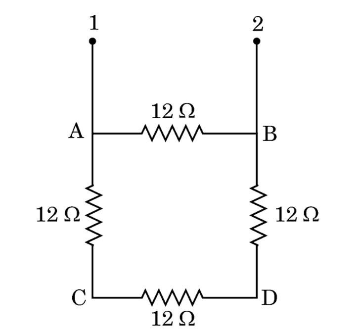
(Square ABCD with resistors on each side. Points 1 and 2 are ... wait, diagram description needed. Usually opposite corners or adjacent? Assuming standard Bridge or Series/Parallel. If points 1 and 2 are across one side e.g., A and B, then 12 || 36. If diagonal, 24 || 24.)
Looking at image crop: Points 1 and 2 are terminals connected to... looks like a vertical feed to A and B? Actually, the text says "network between two points 1 and 2". The diagram shows 1 and 2 connected to Top Left and Top Right? No, they are external leads. A and B are nodes. Let's assume standard "Square Loop" problem.
If inputs are at A and B (one side):
Path 1: A to B (Direct) = \(12 \Omega\).
Path 2: A-C-D-B = \(12+12+12 = 36 \Omega\).
Result: \(12 || 36 = \frac{12 \times 36}{12+36} = \frac{432}{48} = 9 \Omega\).
Let's check options: (C) 9 \(\Omega\). This matches.
Correct Option: (C)
(Square ABCD with resistors on each side. Points 1 and 2 are ... wait, diagram description needed. Usually opposite corners or adjacent? Assuming standard Bridge or Series/Parallel. If points 1 and 2 are across one side e.g., A and B, then 12 || 36. If diagonal, 24 || 24.)
Looking at image crop: Points 1 and 2 are terminals connected to... looks like a vertical feed to A and B? Actually, the text says "network between two points 1 and 2". The diagram shows 1 and 2 connected to Top Left and Top Right? No, they are external leads. A and B are nodes. Let's assume standard "Square Loop" problem.
If inputs are at A and B (one side):
Path 1: A to B (Direct) = \(12 \Omega\).
Path 2: A-C-D-B = \(12+12+12 = 36 \Omega\).
Result: \(12 || 36 = \frac{12 \times 36}{12+36} = \frac{432}{48} = 9 \Omega\).
Let's check options: (C) 9 \(\Omega\). This matches.
Correct Option: (C)
Analysis:
The circuit forms two parallel branches between points A and B (assuming 1 and 2 connect there):
1. Upper branch (Resistance of arm AB) = \(12 \Omega\).
2. Lower branch (series combination of AC, CD, DB) = \(12 + 12 + 12 = 36 \Omega\).
Equivalent Resistance \(R_{eq} = \frac{12 \times 36}{12 + 36} = \frac{12 \times 36}{48} = 9 \Omega\).
Correct Option: (C)
The circuit forms two parallel branches between points A and B (assuming 1 and 2 connect there):
1. Upper branch (Resistance of arm AB) = \(12 \Omega\).
2. Lower branch (series combination of AC, CD, DB) = \(12 + 12 + 12 = 36 \Omega\).
Equivalent Resistance \(R_{eq} = \frac{12 \times 36}{12 + 36} = \frac{12 \times 36}{48} = 9 \Omega\).
Correct Option: (C)
1 Mark
Q11. An electric bulb is connected to a power
supply of 220 V. If the current drawn by the bulb from the supply is 500 mA, the power of the bulb is :
Calculation:
\(V = 220 \text{ V}\).
\(I = 500 \text{ mA} = 0.5 \text{ A}\).
Power \(P = V \times I = 220 \times 0.5 = 110 \text{ W}\).
Correct Option: (B)
\(V = 220 \text{ V}\).
\(I = 500 \text{ mA} = 0.5 \text{ A}\).
Power \(P = V \times I = 220 \times 0.5 = 110 \text{ W}\).
Correct Option: (B)
1 Mark
Q12. Four identical resistors of \(12 \ \Omega\)
each are connected in series to form a square ABCD as shown in the figure. The resistance of the network
between the two points 1 and 2 is :
(Square ABCD with resistors on each side. Points 1 and 2 are ... wait, diagram description needed. Usually opposite corners or adjacent? Assuming standard Bridge or Series/Parallel. If points 1 and 2 are across one side e.g., A and B, then 12 || 36. If diagonal, 24 || 24.)
Looking at image crop: Points 1 and 2 are terminals connected to... looks like a vertical feed to A and B? Actually, the text says "network between two points 1 and 2". The diagram shows 1 and 2 connected to Top Left and Top Right? No, they are external leads. A and B are nodes. Let's assume standard "Square Loop" problem.
If inputs are at A and B (one side):
Path 1: A to B (Direct) = \(12 \Omega\).
Path 2: A-C-D-B = \(12+12+12 = 36 \Omega\).
Result: \(12 || 36 = \frac{12 \times 36}{12+36} = \frac{432}{48} = 9 \Omega\).
Let's check options: (C) 9 \(\Omega\). This matches.
Correct Option: (C)
(Square ABCD with resistors on each side. Points 1 and 2 are ... wait, diagram description needed. Usually opposite corners or adjacent? Assuming standard Bridge or Series/Parallel. If points 1 and 2 are across one side e.g., A and B, then 12 || 36. If diagonal, 24 || 24.)
Looking at image crop: Points 1 and 2 are terminals connected to... looks like a vertical feed to A and B? Actually, the text says "network between two points 1 and 2". The diagram shows 1 and 2 connected to Top Left and Top Right? No, they are external leads. A and B are nodes. Let's assume standard "Square Loop" problem.
If inputs are at A and B (one side):
Path 1: A to B (Direct) = \(12 \Omega\).
Path 2: A-C-D-B = \(12+12+12 = 36 \Omega\).
Result: \(12 || 36 = \frac{12 \times 36}{12+36} = \frac{432}{48} = 9 \Omega\).
Let's check options: (C) 9 \(\Omega\). This matches.
Correct Option: (C)
Analysis:
The circuit forms two parallel branches between points A and B (assuming 1 and 2 connect there):
1. Upper branch (Resistance of arm AB) = \(12 \Omega\).
2. Lower branch (series combination of AC, CD, DB) = \(12 + 12 + 12 = 36 \Omega\).
Equivalent Resistance \(R_{eq} = \frac{12 \times 36}{12 + 36} = \frac{12 \times 36}{48} = 9 \Omega\).
Correct Option: (C)
The circuit forms two parallel branches between points A and B (assuming 1 and 2 connect there):
1. Upper branch (Resistance of arm AB) = \(12 \Omega\).
2. Lower branch (series combination of AC, CD, DB) = \(12 + 12 + 12 = 36 \Omega\).
Equivalent Resistance \(R_{eq} = \frac{12 \times 36}{12 + 36} = \frac{12 \times 36}{48} = 9 \Omega\).
Correct Option: (C)
1 Mark
Q19. Assertion (A): The bending
of a wire in the form of a coil of several turns does not affect its electrical resistance.
Reason (R): The electrical resistance of a wire is directly proportional to its electrical resistivity.
Reason (R): The electrical resistance of a wire is directly proportional to its electrical resistivity.
Analysis:
- Assertion: True. Resistance depends on length, area, and material. Bending doesn't change these intrinsic dimensions (though inductance changes, DC resistance remains same).
- Reason: False statement structure? Resistance is proportional to resistivity \(\rho\), yes. But R explains A?
Actually, Resistance DOES change if you consider "coil" vs "straight" in AC, but in DC context (10th level), simply bending a wire doesn't change its length or area, so R is constant. Reason says \(R \propto \rho\). This is true.
Does R explain A? Why does bending not affect R? Because L and A don't change. R mentions rho. It doesn't strictly explain "bending".
However, usually strictly speaking:
A: True.
R: True.
Is R correct explanation? No, R is about material property. A is about geometry/shape.
Correct Option: (B) Both True, R not correct explanation.
- Assertion: True. Resistance depends on length, area, and material. Bending doesn't change these intrinsic dimensions (though inductance changes, DC resistance remains same).
- Reason: False statement structure? Resistance is proportional to resistivity \(\rho\), yes. But R explains A?
Actually, Resistance DOES change if you consider "coil" vs "straight" in AC, but in DC context (10th level), simply bending a wire doesn't change its length or area, so R is constant. Reason says \(R \propto \rho\). This is true.
Does R explain A? Why does bending not affect R? Because L and A don't change. R mentions rho. It doesn't strictly explain "bending".
However, usually strictly speaking:
A: True.
R: True.
Is R correct explanation? No, R is about material property. A is about geometry/shape.
Correct Option: (B) Both True, R not correct explanation.
2 Marks
Q26. How and why is an electric fuse used in an
electric circuit ? Briefly describe its function.
Electric Fuse:
- How: Connected in series with the live wire.
- Why: To protect appliances and circuits from damage due to overloading or short-circuiting.
- Function: It has a wire of low melting point. When current exceeds a safe limit, the heat generated (\(H=I^2Rt\)) melts the fuse wire, breaking the circuit and stopping the current flow.
- How: Connected in series with the live wire.
- Why: To protect appliances and circuits from damage due to overloading or short-circuiting.
- Function: It has a wire of low melting point. When current exceeds a safe limit, the heat generated (\(H=I^2Rt\)) melts the fuse wire, breaking the circuit and stopping the current flow.
3 Marks
Q32. Three resistors of \(2 \ \Omega\), \(3 \
\Omega\) and \(6 \ \Omega\) are connected in (i) series, and (ii) parallel. Draw the arrangements of the
resistors and find the equivalent resistance of each arrangement.
(i) Series:
\(R_{eq} = R_1 + R_2 + R_3 = 2 + 3 + 6 = 11 \ \Omega\).
(Diagram: Three resistors in a line).
(ii) Parallel:
\(\frac{1}{R_{eq}} = \frac{1}{2} + \frac{1}{3} + \frac{1}{6}\).
LCM of 2, 3, 6 is 6.
\(\frac{1}{R_{eq}} = \frac{3 + 2 + 1}{6} = \frac{6}{6} = 1\).
\(R_{eq} = 1 \ \Omega\).
(Diagram: Three resistors across two points).
\(R_{eq} = R_1 + R_2 + R_3 = 2 + 3 + 6 = 11 \ \Omega\).
(Diagram: Three resistors in a line).
(ii) Parallel:
\(\frac{1}{R_{eq}} = \frac{1}{2} + \frac{1}{3} + \frac{1}{6}\).
LCM of 2, 3, 6 is 6.
\(\frac{1}{R_{eq}} = \frac{3 + 2 + 1}{6} = \frac{6}{6} = 1\).
\(R_{eq} = 1 \ \Omega\).
(Diagram: Three resistors across two points).
2 Marks
Q22. (a) Consider two lamps A and B of rating 50
W; 220 V and 25 W; 220 V respectively. Find the ratio of the resistances of the two lamps (i.e. \(R_A :
R_B\)).
OR
(b) Heat produced per second due to a current in a resistor of 4 \(\Omega\) is 400 joules. Calculate the potential difference across the resistor.
OR
(b) Heat produced per second due to a current in a resistor of 4 \(\Omega\) is 400 joules. Calculate the potential difference across the resistor.
(a) Ratio of Resistances:
Power \(P = \frac{V^2}{R} \Rightarrow R = \frac{V^2}{P}\).
\(R_A = \frac{220^2}{50}\), \(R_B = \frac{220^2}{25}\).
Ratio \(\frac{R_A}{R_B} = \frac{220^2/50}{220^2/25} = \frac{25}{50} = \frac{1}{2}\).
Ratio is 1:2.
(b) Potential Difference:
Heat per second (Power) \(P = 400\) J/s = 400 W.
\(R = 4 \ \Omega\).
\(P = \frac{V^2}{R} \Rightarrow V^2 = P \times R = 400 \times 4 = 1600\).
\(V = \sqrt{1600} = 40\) V.
Potential Difference = 40 V.
Power \(P = \frac{V^2}{R} \Rightarrow R = \frac{V^2}{P}\).
\(R_A = \frac{220^2}{50}\), \(R_B = \frac{220^2}{25}\).
Ratio \(\frac{R_A}{R_B} = \frac{220^2/50}{220^2/25} = \frac{25}{50} = \frac{1}{2}\).
Ratio is 1:2.
(b) Potential Difference:
Heat per second (Power) \(P = 400\) J/s = 400 W.
\(R = 4 \ \Omega\).
\(P = \frac{V^2}{R} \Rightarrow V^2 = P \times R = 400 \times 4 = 1600\).
\(V = \sqrt{1600} = 40\) V.
Potential Difference = 40 V.
3 Marks
Q27. (a) Define one volt potential difference
between two points in an electric field.
(b) Draw a schematic diagram of an electric circuit of a cell of 1.5 V, 5 \(\Omega\) and 10 \(\Omega\) resistor and a plug key, all connected in series. Calculate the current drawn from the cell when the key is closed.
(b) Draw a schematic diagram of an electric circuit of a cell of 1.5 V, 5 \(\Omega\) and 10 \(\Omega\) resistor and a plug key, all connected in series. Calculate the current drawn from the cell when the key is closed.
(a) One Volt: Potential difference between two points is said to be 1 volt if 1
joule of work is done in moving a positive charge of 1 coulomb from one point to the other.
(b) Schematic Diagram:
Total Resistance \(R = R_1 + R_2 = 5 + 10 = 15 \ \Omega\).
Voltage \(V = 1.5\) V.
Current \(I = \frac{V}{R} = \frac{1.5}{15} = 0.1\) A.
(b) Schematic Diagram:
Solution Diagram
Calculation:Total Resistance \(R = R_1 + R_2 = 5 + 10 = 15 \ \Omega\).
Voltage \(V = 1.5\) V.
Current \(I = \frac{V}{R} = \frac{1.5}{15} = 0.1\) A.
3 Marks
Q28. Consider the following electric circuit
:
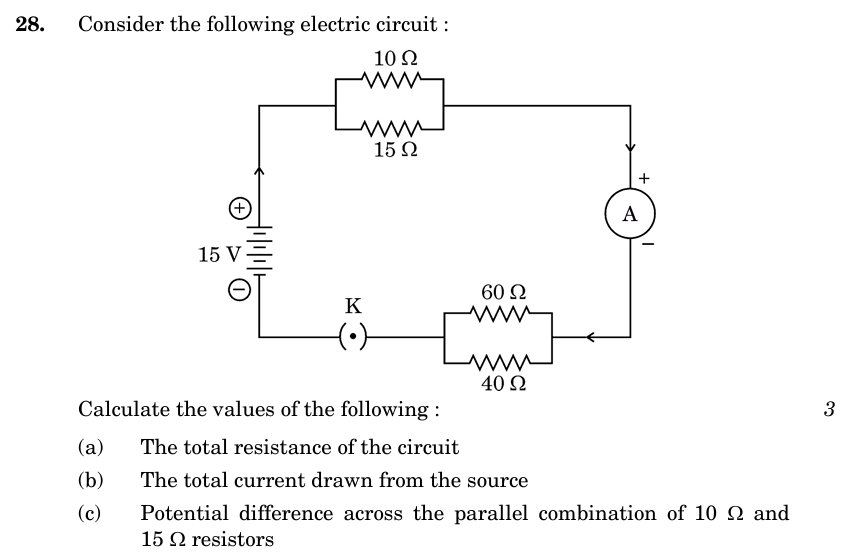 Calculate the values of the following :
(a) The total resistance of the circuit
(b) The total current drawn from the source
(c) Potential difference across the parallel combination of 10 \(\Omega\) and 15 \(\Omega\) resistors.
Calculate the values of the following :(a) The total resistance of the circuit
(b) The total current drawn from the source
(c) Potential difference across the parallel combination of 10 \(\Omega\) and 15 \(\Omega\) resistors.
(a) Total Resistance:
Upper Parallel Group \(R_{p1}\): \(10 \parallel 15\).
\(\frac{1}{R_{p1}} = \frac{1}{10} + \frac{1}{15} = \frac{3+2}{30} = \frac{5}{30} = \frac{1}{6} \Rightarrow R_{p1} = 6 \ \Omega\).
Lower Parallel Group \(R_{p2}\): \(60 \parallel 40\).
\(\frac{1}{R_{p2}} = \frac{1}{60} + \frac{1}{40} = \frac{2+3}{120} = \frac{5}{120} = \frac{1}{24} \Rightarrow R_{p2} = 24 \ \Omega\).
Groups are in series.
\(R_{total} = R_{p1} + R_{p2} = 6 + 24 = 30 \ \Omega\).
(b) Total Current:
\(V = 15\) V.
\(I = \frac{V}{R_{total}} = \frac{15}{30} = 0.5\) A.
(c) PD across 10 \(\Omega\) and 15 \(\Omega\):
This is \(V_{p1}\) across the upper group.
\(V_{p1} = I \times R_{p1} = 0.5 \times 6 = 3\) V.
Upper Parallel Group \(R_{p1}\): \(10 \parallel 15\).
\(\frac{1}{R_{p1}} = \frac{1}{10} + \frac{1}{15} = \frac{3+2}{30} = \frac{5}{30} = \frac{1}{6} \Rightarrow R_{p1} = 6 \ \Omega\).
Lower Parallel Group \(R_{p2}\): \(60 \parallel 40\).
\(\frac{1}{R_{p2}} = \frac{1}{60} + \frac{1}{40} = \frac{2+3}{120} = \frac{5}{120} = \frac{1}{24} \Rightarrow R_{p2} = 24 \ \Omega\).
Groups are in series.
\(R_{total} = R_{p1} + R_{p2} = 6 + 24 = 30 \ \Omega\).
(b) Total Current:
\(V = 15\) V.
\(I = \frac{V}{R_{total}} = \frac{15}{30} = 0.5\) A.
(c) PD across 10 \(\Omega\) and 15 \(\Omega\):
This is \(V_{p1}\) across the upper group.
\(V_{p1} = I \times R_{p1} = 0.5 \times 6 = 3\) V.
2 Marks
Q34(c). (i) What is the function of the earth
wire ? State the advantage of the earth wire in domestic electric appliances such as electric iron.
OR
(ii) List two precautions to be taken to avoid electrical accidents. State how these precautions prevent possible damage to the circuit/appliance.
OR
(ii) List two precautions to be taken to avoid electrical accidents. State how these precautions prevent possible damage to the circuit/appliance.
(i) Earth Wire:
Function: It provides a low-resistance conducting path for the current.
Advantage: If there is any leakage of current to the metallic body of the appliance, the current flows to the earth, preventing severe electric shock to the user and operating the fuse.
(ii) Precautions:
1. Use of Fuse/MCB: Prevents damage due to overloading/short-circuit by breaking the circuit.
2. Proper Earthing: Prevents electric shock from metallic appliances.
(Alternatively: Use of good quality wires/insulation to prevent short circuits).
Function: It provides a low-resistance conducting path for the current.
Advantage: If there is any leakage of current to the metallic body of the appliance, the current flows to the earth, preventing severe electric shock to the user and operating the fuse.
(ii) Precautions:
1. Use of Fuse/MCB: Prevents damage due to overloading/short-circuit by breaking the circuit.
2. Proper Earthing: Prevents electric shock from metallic appliances.
(Alternatively: Use of good quality wires/insulation to prevent short circuits).
3 Marks
Q29. (a) Two resistors \(R_1\) and \(R_2\) are
connected in series. Derive an expression for the equivalent resistance of the combination.
(b) In an electric circuit, two resistors of \(12 \ \Omega\) each are connected in parallel to a 6 V battery. Find the current drawn from the battery.
(b) In an electric circuit, two resistors of \(12 \ \Omega\) each are connected in parallel to a 6 V battery. Find the current drawn from the battery.
(a) Series Combination Derivation:
1. Consider two resistors \(R_1\) and \(R_2\) connected in series.
2. Current \(I\) remains same through both.
3. Potential difference \(V\) divides across them (\(V = V_1 + V_2\)).
From Ohm's Law: \(V_1 = I R_1\), \(V_2 = I R_2\).
Total \(V = I (R_1 + R_2)\).
Equivalent resistance \(R_s\) is such that \(V = I R_s\).
Comparing: \(I R_s = I (R_1 + R_2) \\Rightarrow R_s = R_1 + R_2\).
(b) Numerical:
Given: \(R_1 = R_2 = 12 \ \Omega\) (Parallel). \(V = 6\) V.
Equivalent Resistance \(R_p\):
\(\frac{1}{R_p} = \frac{1}{12} + \frac{1}{12} = \frac{2}{12} = \frac{1}{6}\).
\(R_p = 6 \ \Omega\).
Current \(I = \frac{V}{R_p} = \frac{6}{6} = 1\) A.
1. Consider two resistors \(R_1\) and \(R_2\) connected in series.
2. Current \(I\) remains same through both.
3. Potential difference \(V\) divides across them (\(V = V_1 + V_2\)).
From Ohm's Law: \(V_1 = I R_1\), \(V_2 = I R_2\).
Total \(V = I (R_1 + R_2)\).
Equivalent resistance \(R_s\) is such that \(V = I R_s\).
Comparing: \(I R_s = I (R_1 + R_2) \\Rightarrow R_s = R_1 + R_2\).
(b) Numerical:
Given: \(R_1 = R_2 = 12 \ \Omega\) (Parallel). \(V = 6\) V.
Equivalent Resistance \(R_p\):
\(\frac{1}{R_p} = \frac{1}{12} + \frac{1}{12} = \frac{2}{12} = \frac{1}{6}\).
\(R_p = 6 \ \Omega\).
Current \(I = \frac{V}{R_p} = \frac{6}{6} = 1\) A.
5 Marks
Q33. (a) (i) Define electric power. Express it in
terms of potential difference V and resistance R.
(ii) An electrical fuse is rated at 2 A. What is meant by this statement?
(iii) An electric iron of 1 kW is operated at 220 V. Find which of the following fuses that respectively rated at 3 A, 5 A and 10 A can be used in it.
OR
(b) (i) State Joule's law of heating so express it mathematically.
(ii) With the help of a suitable circuit diagram, prove that the heat produced in a resistor is given by \(H = I^2Rt\).
(iii) Why are the heating elements of electric toasters and electric irons made of an alloy rather than a pure metal ?
(ii) An electrical fuse is rated at 2 A. What is meant by this statement?
(iii) An electric iron of 1 kW is operated at 220 V. Find which of the following fuses that respectively rated at 3 A, 5 A and 10 A can be used in it.
OR
(b) (i) State Joule's law of heating so express it mathematically.
(ii) With the help of a suitable circuit diagram, prove that the heat produced in a resistor is given by \(H = I^2Rt\).
(iii) Why are the heating elements of electric toasters and electric irons made of an alloy rather than a pure metal ?
(a) (i) Electric Power: Rate at which electric energy is
consumed/dissipated.
\(P = VI\). Using \(I = V/R\), \(P = V(V/R) = \frac{V^2}{R}\).
(a) (ii) Fuse Rating 2A: It means the maximum current that can flow through the fuse without melting it is 2 A. If current exceeds 2 A, the fuse wire will melt and break the circuit.
(a) (iii) Fuse for Electric Iron:
\(P = 1 \text{ kW} = 1000\) W. \(V = 220\) V.
Current \(I = \frac{P}{V} = \frac{1000}{220} \approx 4.54\) A.
Fuse required should be slightly greater than 4.54 A.
Available fuses: 3 A, 5 A, 10 A.
Selected Fuse: 5 A.
(b) (i) Joule's Law of Heating: Heat produced in a resistor is directly proportional to:
- Square of current (\(I^2\))
- Resistance (\(R\))
- Time (\(t\)).
Mathematically: \(H = I^2 R t\).
(b) (ii) Proof:
Consider resistor R, current I flows for time t.
Charge \(Q = I \times t\).
Work done to move charge Q across potential difference V is \(W = V \times Q\).
\(W = V \times (It)\). Since \(V = IR\), \(W = (IR)It = I^2 R t\).
This work is converted to Heat (H). So \(H = I^2 R t\).
(Circuit Diagram would involve Battery, Key, Ammeter in series with R, Voltmeter parallel to R).
(b) (iii) Alloys for Heating Elements:
1. Higher resistivity than pure metals (produces more heat).
2. Do not oxidize (burn) easily at high temperatures.
\(P = VI\). Using \(I = V/R\), \(P = V(V/R) = \frac{V^2}{R}\).
(a) (ii) Fuse Rating 2A: It means the maximum current that can flow through the fuse without melting it is 2 A. If current exceeds 2 A, the fuse wire will melt and break the circuit.
(a) (iii) Fuse for Electric Iron:
\(P = 1 \text{ kW} = 1000\) W. \(V = 220\) V.
Current \(I = \frac{P}{V} = \frac{1000}{220} \approx 4.54\) A.
Fuse required should be slightly greater than 4.54 A.
Available fuses: 3 A, 5 A, 10 A.
Selected Fuse: 5 A.
(b) (i) Joule's Law of Heating: Heat produced in a resistor is directly proportional to:
- Square of current (\(I^2\))
- Resistance (\(R\))
- Time (\(t\)).
Mathematically: \(H = I^2 R t\).
(b) (ii) Proof:
Consider resistor R, current I flows for time t.
Charge \(Q = I \times t\).
Work done to move charge Q across potential difference V is \(W = V \times Q\).
\(W = V \times (It)\). Since \(V = IR\), \(W = (IR)It = I^2 R t\).
This work is converted to Heat (H). So \(H = I^2 R t\).
(Circuit Diagram would involve Battery, Key, Ammeter in series with R, Voltmeter parallel to R).
(b) (iii) Alloys for Heating Elements:
1. Higher resistivity than pure metals (produces more heat).
2. Do not oxidize (burn) easily at high temperatures.
1 Mark
Q17. Two bulbs are rated 200 V-100 W and 200 V-50
W. Their resistances are \(R_1\) and \(R_2\) respectively. The ratio \(\frac{R_1}{R_2}\) is :
Formula: \(P = \frac{V^2}{R} \Rightarrow R = \frac{V^2}{P}\).
\(R_1 = \frac{200^2}{100} = 400 \ \Omega\).
\(R_2 = \frac{200^2}{50} = 800 \ \Omega\).
Ratio \(\frac{R_1}{R_2} = \frac{400}{800} = \frac{1}{2}\).
Correct Option: (B)
\(R_1 = \frac{200^2}{100} = 400 \ \Omega\).
\(R_2 = \frac{200^2}{50} = 800 \ \Omega\).
Ratio \(\frac{R_1}{R_2} = \frac{400}{800} = \frac{1}{2}\).
Correct Option: (B)
2 Marks
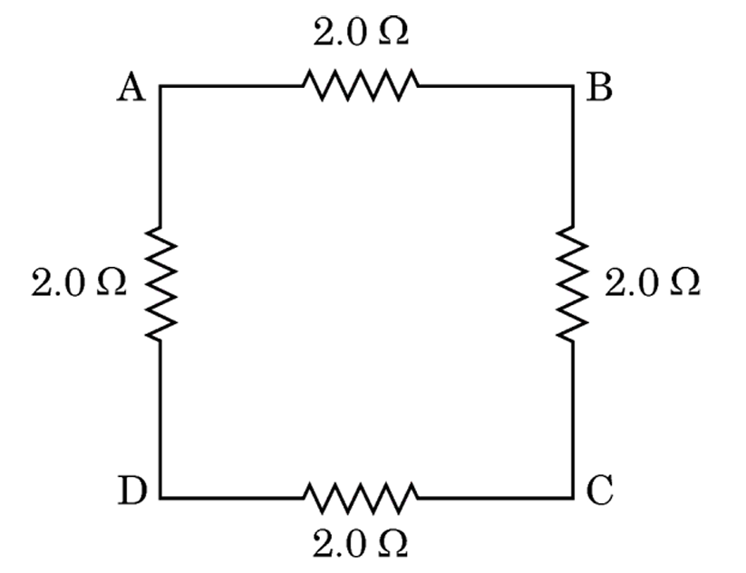
Q26. Four resistors, each of resistance \(2.0 \
\Omega\), are joined end to end to form a square ABCD as shown. Using appropriate formula, determine the
equivalent resistance of the combination between its two ends A and B.
 26.png"
class="question-image" alt="2025-31-3-QuestionNumber26.png" style="max-width: 80%; max-height: 60vh;
object-fit: contain; height: auto; display: block; margin: 10px auto; border-radius: 8px;">
(Diagram shows Square ABCD with 2 Ohm on each side. Terminals at A and B).
26.png"
class="question-image" alt="2025-31-3-QuestionNumber26.png" style="max-width: 80%; max-height: 60vh;
object-fit: contain; height: auto; display: block; margin: 10px auto; border-radius: 8px;">
(Diagram shows Square ABCD with 2 Ohm on each side. Terminals at A and B).
26.png"
class="question-image" alt="2025-31-3-QuestionNumber26.png" style="max-width: 80%; max-height: 60vh;
object-fit: contain; height: auto; display: block; margin: 10px auto; border-radius: 8px;">
(Diagram shows Square ABCD with 2 Ohm on each side. Terminals at A and B).
Analysis:
Resistance of each arm = \(2.0 \ \Omega\).
Connection between A and B:
1. Path 1 (Upper Branch): Side AB only. Resistance \(R_1 = 2.0 \ \Omega\).
2. Path 2 (Lower Branch via D and C): Sides AD, DC, CB are in series.
Resistance \(R_2 = 2.0 + 2.0 + 2.0 = 6.0 \ \Omega\).
Now, \(R_1\) and \(R_2\) are in parallel across A and B.
\(\frac{1}{R_{eq}} = \frac{1}{R_1} + \frac{1}{R_2} = \frac{1}{2} + \frac{1}{6}\)
\(\frac{1}{R_{eq}} = \frac{3+1}{6} = \frac{4}{6} = \frac{2}{3}\)
\(R_{eq} = \frac{3}{2} = 1.5 \ \Omega\).
Equivalent Resistance: \(1.5 \ \Omega\).
Resistance of each arm = \(2.0 \ \Omega\).
Connection between A and B:
1. Path 1 (Upper Branch): Side AB only. Resistance \(R_1 = 2.0 \ \Omega\).
2. Path 2 (Lower Branch via D and C): Sides AD, DC, CB are in series.
Resistance \(R_2 = 2.0 + 2.0 + 2.0 = 6.0 \ \Omega\).
Now, \(R_1\) and \(R_2\) are in parallel across A and B.
\(\frac{1}{R_{eq}} = \frac{1}{R_1} + \frac{1}{R_2} = \frac{1}{2} + \frac{1}{6}\)
\(\frac{1}{R_{eq}} = \frac{3+1}{6} = \frac{4}{6} = \frac{2}{3}\)
\(R_{eq} = \frac{3}{2} = 1.5 \ \Omega\).
Equivalent Resistance: \(1.5 \ \Omega\).
5 Marks
Q37. As shown in the diagram, an electric circuit
consisting of an ammeter, a voltmeter, 4 cells of 1.5 V each, a plug key with a gap XY was set up.
Voltmeter and ammeter readings were recorded in the observation table for four arrangements as given
below :
Arrangement No. 1 � only resistor \(R_1\) in gap XY
Arrangement No. 2 � only resistor \(R_2\) in gap XY
Arrangement No. 3 � Resistors \(R_1\) and \(R_2\) in series in gap XY
Arrangement No. 4 � Resistors \(R_1\) and \(R_2\) in parallel in gap XY
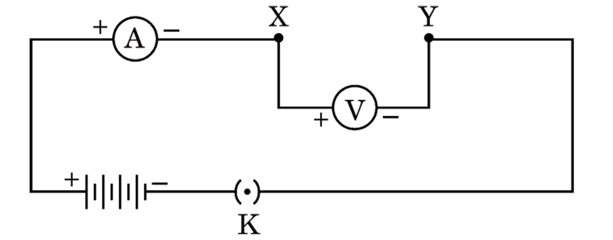 mage.png"
class="question-image" alt="2025-31-3-QuestionNumber37FirstImage.png" style="max-width: 80%; max-height:
60vh; object-fit: contain; height: auto; display: block; margin: 10px auto; border-radius: 8px;">
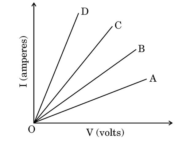
Based on the observations, four V � I graphs A, B, C and D as shown in figure were drawn. Study these
graphs.
mage.png"
class="question-image" alt="2025-31-3-QuestionNumber37FirstImage.png" style="max-width: 80%; max-height:
60vh; object-fit: contain; height: auto; display: block; margin: 10px auto; border-radius: 8px;">
Based on the observations, four V � I graphs A, B, C and D as shown in figure were drawn. Study these
graphs.
 ndimage.png"
class="question-image" alt="2025-31-3-QuestionNumber37secondimage.png" style="max-width: 80%;
max-height: 60vh; object-fit: contain; height: auto; display: block; margin: 10px auto; border-radius:
8px;">
(a) Which one of the graphs represents the series combination of \(R_1\) and \(R_2\) ?
ndimage.png"
class="question-image" alt="2025-31-3-QuestionNumber37secondimage.png" style="max-width: 80%;
max-height: 60vh; object-fit: contain; height: auto; display: block; margin: 10px auto; border-radius:
8px;">
(a) Which one of the graphs represents the series combination of \(R_1\) and \(R_2\) ?
(b) Which one of the graphs represents the parallel combination of \(R_1\) and \(R_2\) ?
(c) (i) Show an arrangement of three resistors, each of resistance \(10 \ \Omega\), so that the combination has a resistance of \(15 \ \Omega\). Give justification for your answer.
OR
(c) (ii) A battery of 6 V is connected with a series combination of five resistors of 0.1 \(\Omega\), 0.2 \(\Omega\), 0.3 \(\Omega\), 0.4 \(\Omega\) and 0.5 \(\Omega\). How much current would flow through the 0.3 \(\Omega\) resistor ? Justify your answer.
Arrangement No. 1 � only resistor \(R_1\) in gap XY
Arrangement No. 2 � only resistor \(R_2\) in gap XY
Arrangement No. 3 � Resistors \(R_1\) and \(R_2\) in series in gap XY
Arrangement No. 4 � Resistors \(R_1\) and \(R_2\) in parallel in gap XY
mage.png"
class="question-image" alt="2025-31-3-QuestionNumber37FirstImage.png" style="max-width: 80%; max-height:
60vh; object-fit: contain; height: auto; display: block; margin: 10px auto; border-radius: 8px;">
Based on the observations, four V � I graphs A, B, C and D as shown in figure were drawn. Study these
graphs.ndimage.png"
class="question-image" alt="2025-31-3-QuestionNumber37secondimage.png" style="max-width: 80%;
max-height: 60vh; object-fit: contain; height: auto; display: block; margin: 10px auto; border-radius:
8px;">
(a) Which one of the graphs represents the series combination of \(R_1\) and \(R_2\) ?(b) Which one of the graphs represents the parallel combination of \(R_1\) and \(R_2\) ?
(c) (i) Show an arrangement of three resistors, each of resistance \(10 \ \Omega\), so that the combination has a resistance of \(15 \ \Omega\). Give justification for your answer.
OR
(c) (ii) A battery of 6 V is connected with a series combination of five resistors of 0.1 \(\Omega\), 0.2 \(\Omega\), 0.3 \(\Omega\), 0.4 \(\Omega\) and 0.5 \(\Omega\). How much current would flow through the 0.3 \(\Omega\) resistor ? Justify your answer.
Analysis of Graphs:
Y-axis: Current (I), X-axis: Potential Difference (V).
Slope of I-V graph = \(\frac{I}{V} = \frac{1}{R}\).
So, Higher Slope \(\rightarrow\) Lower Resistance.
Lower Slope \(\rightarrow\) Higher Resistance.
Resistances: Series (\(R_s > R_1, R_2\)) has Maximum Resistance. Parallel (\(R_p < R_1, R_2\)) has Minimum Resistance.
Graph A has Minimum Slope \(\rightarrow\) Maximum Resistance (Series).
Graph D has Maximum Slope \(\rightarrow\) Minimum Resistance (Parallel).
(a) Series Combination: Graph A.
(b) Parallel Combination: Graph D.
(c) (i) Arrangement for 15 \(\Omega\):
connect two \(10 \ \Omega\) resistors in parallel and one \(10 \ \Omega\) in series with them.
\(R_p = \frac{10 \times 10}{10 + 10} = \frac{100}{20} = 5 \ \Omega\).
Total \(R = R_p + 10 = 5 + 10 = 15 \ \Omega\).
(c) (ii) Series Circuit:
Total Resistance \(R = 0.1 + 0.2 + 0.3 + 0.4 + 0.5 = 1.5 \ \Omega\).
Voltage \(V = 6\) V.
Current \(I = \frac{V}{R} = \frac{6}{1.5} = 4\) A.
Justification: In a series circuit, the current remains the same through all components. So, 4 A flows through the \(0.3 \ \Omega\) resistor.
Y-axis: Current (I), X-axis: Potential Difference (V).
Slope of I-V graph = \(\frac{I}{V} = \frac{1}{R}\).
So, Higher Slope \(\rightarrow\) Lower Resistance.
Lower Slope \(\rightarrow\) Higher Resistance.
Resistances: Series (\(R_s > R_1, R_2\)) has Maximum Resistance. Parallel (\(R_p < R_1, R_2\)) has Minimum Resistance.
Graph A has Minimum Slope \(\rightarrow\) Maximum Resistance (Series).
Graph D has Maximum Slope \(\rightarrow\) Minimum Resistance (Parallel).
(a) Series Combination: Graph A.
(b) Parallel Combination: Graph D.
(c) (i) Arrangement for 15 \(\Omega\):
connect two \(10 \ \Omega\) resistors in parallel and one \(10 \ \Omega\) in series with them.
\(R_p = \frac{10 \times 10}{10 + 10} = \frac{100}{20} = 5 \ \Omega\).
Total \(R = R_p + 10 = 5 + 10 = 15 \ \Omega\).
(c) (ii) Series Circuit:
Total Resistance \(R = 0.1 + 0.2 + 0.3 + 0.4 + 0.5 = 1.5 \ \Omega\).
Voltage \(V = 6\) V.
Current \(I = \frac{V}{R} = \frac{6}{1.5} = 4\) A.
Justification: In a series circuit, the current remains the same through all components. So, 4 A flows through the \(0.3 \ \Omega\) resistor.
1 Mark
Q5. A piece of wire of resistance 'R' is cut
lengthwise into three identical parts. These parts are then connected in parallel. If the equivalent
resistance of this combination is R', then the value of R/R' is :
Calculation:
Original Resistance (R).
Cut into 3 parts: Each has resistance (r = R/3).
Connected in Parallel: \(\frac{1}{R'} = \frac{1}{r} + \frac{1}{r} + \frac{1}{r} = \frac{3}{r}\).
\(R' = \frac{r}{3} = \frac{R/3}{3} = \frac{R}{9}).
Ratio (R/R' = R / (R/9) = 9\).
Correct Option: (d)
Original Resistance (R).
Cut into 3 parts: Each has resistance (r = R/3).
Connected in Parallel: \(\frac{1}{R'} = \frac{1}{r} + \frac{1}{r} + \frac{1}{r} = \frac{3}{r}\).
\(R' = \frac{r}{3} = \frac{R/3}{3} = \frac{R}{9}).
Ratio (R/R' = R / (R/9) = 9\).
Correct Option: (d)
1 Mark
Q10. The minimum number of identical bulbs of
rating 4V; 6W, that can work safely with desired brightness, when connected in series with a 240 V mains
supply is :
Series Connection:
Voltage across each bulb = 4 V.
Total Supply (V = 240) V.
Let number of bulbs be (n).
(n \times 4 = 240 \Rightarrow n = 60\).
Correct Option: (c)
Voltage across each bulb = 4 V.
Total Supply (V = 240) V.
Let number of bulbs be (n).
(n \times 4 = 240 \Rightarrow n = 60\).
Correct Option: (c)
1 Mark
Q11. An electric bulb is rated 220 V; 11W. The
resistance of its filament when it glows with a power supply of 220 V is :
Formula: \(P = \frac{V^2}{R} \Rightarrow R = \frac{V^2}{P}\).
\(R = \frac{220 \times 220}{11} = 20 \times 220 = 4400 \ \Omega\).
Correct Option: (a)
\(R = \frac{220 \times 220}{11} = 20 \times 220 = 4400 \ \Omega\).
Correct Option: (a)
3 Marks
Q32. Define the term "potential difference"
between two points in an electric circuit carrying current. Name and define its S.I. unit. Also express
it in terms of S.I. unit of work and charge.
Potential Difference (V): Work done to move a unit charge from
one point to another in current carrying circuit.
SI Unit: Volt (V).
Definition of 1 Volt: When 1 Joule of work is done to move a charge of 1 Coulomb from one point to another, the PD is 1 Volt.
Expression: \( V (\text{volt}) = \frac{W (\text{Joule})}{Q (\text{Coulomb})} \) or \( 1 \text{ V} = 1 \text{ J C}^{-1} \).
SI Unit: Volt (V).
Definition of 1 Volt: When 1 Joule of work is done to move a charge of 1 Coulomb from one point to another, the PD is 1 Volt.
Expression: \( V (\text{volt}) = \frac{W (\text{Joule})}{Q (\text{Coulomb})} \) or \( 1 \text{ V} = 1 \text{ J C}^{-1} \).
2 Marks
Q22. (A) Determine the maximum and minimum
resistance which can be obtained by joining five resistors of \(\frac{1}{5} \Omega\) each.
OR
(B) Calculate potential difference across a \(4 \Omega\) resistor that produces 100 J of heat every second.
OR
(B) Calculate potential difference across a \(4 \Omega\) resistor that produces 100 J of heat every second.
(A)
Maximum Resistance (Series): \(R_{max} = n R = 5 \times \frac{1}{5} = 1 \Omega\).
Minimum Resistance (Parallel): \(R_{min} = \frac{R}{n} = \frac{1/5}{5} = \frac{1}{25} \Omega = 0.04 \Omega\).
(B)
Heat \(H = 100\text{ J}\), Time \(t = 1\text{ s}\). Power \(P = 100\text{ W}\).
\(P = \frac{V^2}{R} \Rightarrow 100 = \frac{V^2}{4}\).
\(V^2 = 400 \Rightarrow V = 20\text{ V}\).
Maximum Resistance (Series): \(R_{max} = n R = 5 \times \frac{1}{5} = 1 \Omega\).
Minimum Resistance (Parallel): \(R_{min} = \frac{R}{n} = \frac{1/5}{5} = \frac{1}{25} \Omega = 0.04 \Omega\).
(B)
Heat \(H = 100\text{ J}\), Time \(t = 1\text{ s}\). Power \(P = 100\text{ W}\).
\(P = \frac{V^2}{R} \Rightarrow 100 = \frac{V^2}{4}\).
\(V^2 = 400 \Rightarrow V = 20\text{ V}\).
3 Marks
Q28. The resistance of a wire of 0.01 cm radius
is 7 ohms. If the resistivity of the material of the wire is \(44 \times 10^{-6}\) ohm meter, calculate
the length of the wire.
Radius \(r = 0.01\text{ cm} = 10^{-4}\text{ m}\).
Resistance \(R = 7 \Omega\).
Resistivity \(\rho = 44 \times 10^{-6} \Omega\text{m}\).
Area \(A = \pi r^2 = \frac{22}{7} \times (10^{-4})^2 = \frac{22}{7} \times 10^{-8}\text{ m}^2\).
Formula: \(R = \rho \frac{l}{A} \Rightarrow l = \frac{RA}{\rho}\).
\(l = \frac{7 \times (\frac{22}{7} \times 10^{-8})}{44 \times 10^{-6}}\)
\(l = \frac{22 \times 10^{-8}}{44 \times 10^{-6}} = 0.5 \times 10^{-2}\text{ m} = 0.005\text{ m} = 0.5\text{ cm}\).
(Calculation check: \(22/44 = 0.5\). \(10^{-8}/10^{-6} = 10^{-2}\)).
Resistance \(R = 7 \Omega\).
Resistivity \(\rho = 44 \times 10^{-6} \Omega\text{m}\).
Area \(A = \pi r^2 = \frac{22}{7} \times (10^{-4})^2 = \frac{22}{7} \times 10^{-8}\text{ m}^2\).
Formula: \(R = \rho \frac{l}{A} \Rightarrow l = \frac{RA}{\rho}\).
\(l = \frac{7 \times (\frac{22}{7} \times 10^{-8})}{44 \times 10^{-6}}\)
\(l = \frac{22 \times 10^{-8}}{44 \times 10^{-6}} = 0.5 \times 10^{-2}\text{ m} = 0.005\text{ m} = 0.5\text{ cm}\).
(Calculation check: \(22/44 = 0.5\). \(10^{-8}/10^{-6} = 10^{-2}\)).
3 Marks
Q33. (a) Explain the statement "Potential
difference between two points is 1 volt".
(b) What do the symbols given below represent in an electric circuit ? Write one function of each.
(i) A circle with A inside.
(ii) A zig-zag line with arrow.
(b) What do the symbols given below represent in an electric circuit ? Write one function of each.
(i) A circle with A inside.
(ii) A zig-zag line with arrow.
(a) 1 Volt is the potential difference when 1 Joule of work is done to move a charge of 1 Coulomb
from one point to another.
(b) (i) Ammeter: Measures current. (Connected in series).
(ii) Variable Resistance (Rheostat): To regulate current without changing voltage source.
(b) (i) Ammeter: Measures current. (Connected in series).
(ii) Variable Resistance (Rheostat): To regulate current without changing voltage source.
4 Marks
Q39. Case Study: Study the
circuit shown in which two resistors X and Y of resistances 3 \(\Omega\) and 6 \(\Omega\) respectively
are joined in series with a battery of 2 V.

(I) Draw a circuit diagram showing the above two resistors X and Y joined in parallel with same battery and same ammeter and voltmeter.
(II) In which combination of resistors will the (i) potential difference across X and Y and (ii) current through X and Y, be the same ?
(III) (a) Find the current drawn from the battery by the series combination of the two resistors (X and Y).
OR
(III) (b) Determine the equivalent resistance of the parallel combination of the two resistors (X and Y).
(I) Draw a circuit diagram showing the above two resistors X and Y joined in parallel with same battery and same ammeter and voltmeter.
(II) In which combination of resistors will the (i) potential difference across X and Y and (ii) current through X and Y, be the same ?
(III) (a) Find the current drawn from the battery by the series combination of the two resistors (X and Y).
OR
(III) (b) Determine the equivalent resistance of the parallel combination of the two resistors (X and Y).
(I)
(II) (i) Potential difference is same in Parallel.
(ii) Current is same in Series.
(III) (a) Series: \(R_s = 3 + 6 = 9 \Omega\). \(V = 2 ext{V}\).
\(I = V/R = 2/9 = 0.22\text{ A}\).
(III) (b) Parallel: \(\frac{1}{R_p} = rac{1}{3} + rac{1}{6} = rac{2+1}{6} = rac{3}{6} = rac{1}{2}\).
\(R_p = 2 \Omega\).
Parallel Circuit Diagram
(II) (i) Potential difference is same in Parallel.
(ii) Current is same in Series.
(III) (a) Series: \(R_s = 3 + 6 = 9 \Omega\). \(V = 2 ext{V}\).
\(I = V/R = 2/9 = 0.22\text{ A}\).
(III) (b) Parallel: \(\frac{1}{R_p} = rac{1}{3} + rac{1}{6} = rac{2+1}{6} = rac{3}{6} = rac{1}{2}\).
\(R_p = 2 \Omega\).
Board Exam 2024
Content coming soon for 2024...
Board Exam 2023
Content coming soon for 2023...
Board Exam 2022
Content coming soon for 2022...