Light: Reflection & Refraction
Class 10 Science • Chapter 09 •
Detailed Notes
1. Reflection of Light
Reflection is the phenomenon of bouncing back of light into the same medium when it strikes
a smooth, polished surface (mirror).
%20&%20Convex%20Lens%20(Right).png) Figure 1.0: Key Terms � Concave Mirror (Left) & Convex Lens (Right)
Figure 1.0: Key Terms � Concave Mirror (Left) & Convex Lens (Right)
Laws of Reflection
- Law 1: The angle of incidence (∠i) is always equal to the
angle of reflection (∠r). [∠i = ∠r]
- Law 2: The incident ray, the reflected ray, and the normal at the point of
incidence all lie in the same plane.
Note: Both angles are measured from the Normal
(perpendicular to the surface at point of incidence), NOT from the surface.
Lateral Inversion & Plane Mirror Images
Lateral Inversion: In a plane mirror, the left side of the object appears as the right
side of the image. This is why "AMBULANCE" is written in reverse on ambulances � so it reads correctly
in rear-view mirrors.
Properties of image in a plane mirror:
- Virtual and Erect
- Same size as object
- As far behind mirror as object is in front
- Laterally Inverted
Spherical Mirrors � Key Terms
- Pole (P): Midpoint of reflecting surface of mirror.
- Centre of Curvature (C): Centre of the hollow sphere of which the mirror is a part.
- Radius of Curvature (R): Radius of the sphere; distance from P to C.
- Principal Axis: Line through P and C.
- Principal Focus (F): Point where parallel rays (from infinity) after reflection
meet (Concave) or appear to diverge from (Convex).
- Key Relation: R = 2f (Radius of Curvature = 2 × Focal Length)
Uses of Mirrors:
Concave Mirror: Shaving/make-up mirrors (virtual, magnified), dentist's mirror, solar
furnaces, headlights/torches (reflectors), reflecting telescopes.
Convex Mirror: Rear-view mirrors in vehicles (wide field of view, always erect image),
security mirrors in shops.
New Cartesian Sign Convention
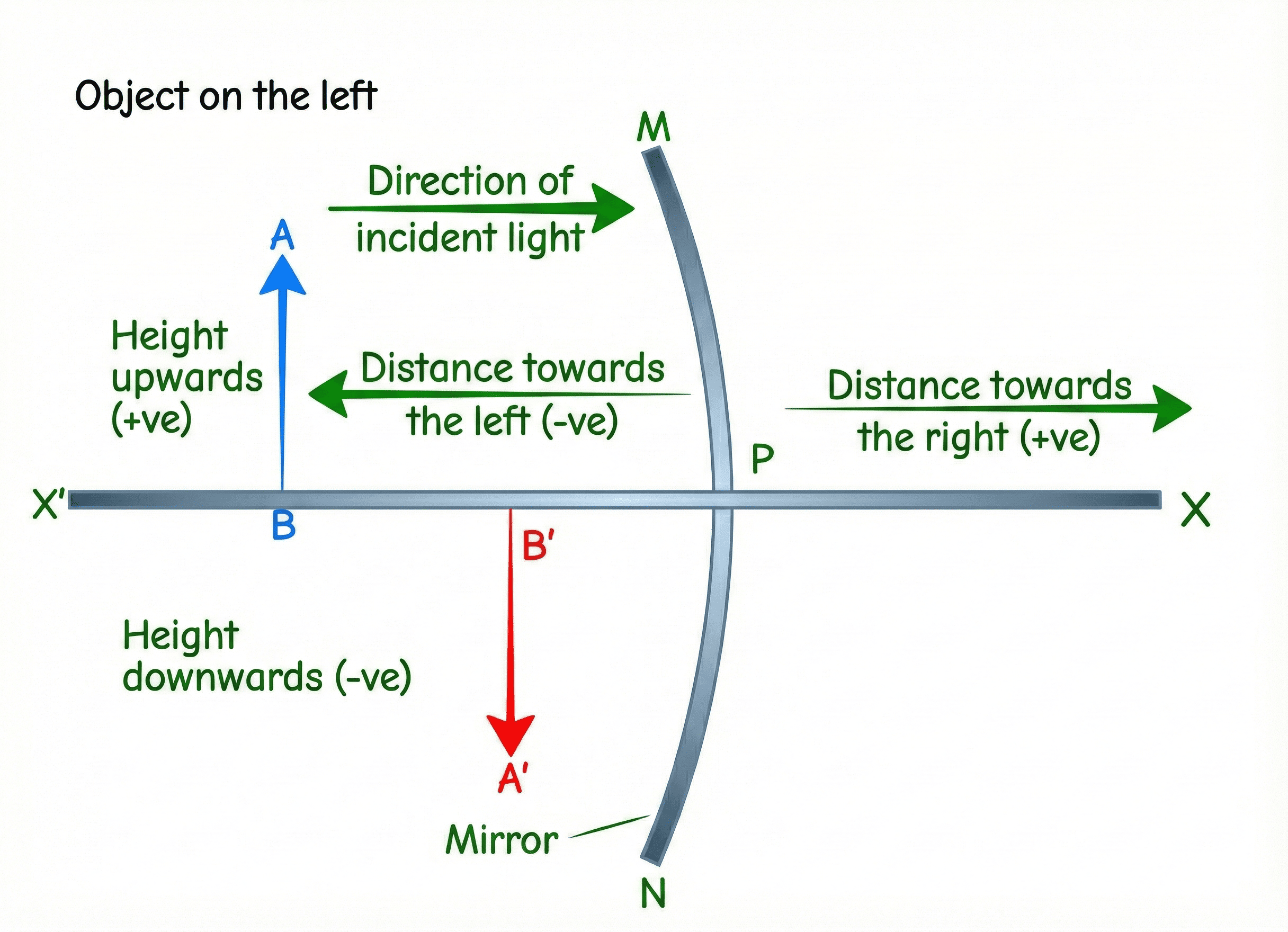 Figure 1.1: New Cartesian Sign Convention for Mirrors
- All distances measured from Pole (P).
- Distances in direction of incident light → Positive (+).
- Distances opposite to incident light → Negative (−).
- Heights above principal axis → Positive (+).
- Heights below principal axis → Negative (−).
- For mirrors: object always placed to the left → u is always negative.
Rules for Ray Tracing (Mirrors)
- A ray parallel to Principal Axis → after reflection, passes through Principal Focus (F).
- A ray passing through Principal Focus (F) → after reflection, becomes parallel to Principal
Axis.
- A ray passing through Centre of Curvature (C) → retraces its path (Normal incidence).
- A ray obliquely incident at Pole (P) → reflects with equal angle (∠i = ∠r).
.png) Figure 1.1b: Rules for Ray Tracing (Mirrors)
Figure 1.1b: Rules for Ray Tracing (Mirrors)
Image Formation by Concave Mirror
.png) Figure 1.2: Image Formation by Concave Mirror
Figure 1.2: Image Formation by Concave Mirror
| Object Position |
Image Position |
Size |
Nature |
| At Infinity |
At Focus F |
Highly Diminished |
Real & Inverted |
| Beyond C |
Between F and C |
Diminished |
Real & Inverted |
| At C |
At C |
Same Size |
Real & Inverted |
| Between F and C |
Beyond C |
Enlarged |
Real & Inverted |
| At Focus F |
At Infinity |
Highly Enlarged |
Real & Inverted |
| Between F and P |
Behind mirror |
Enlarged |
Virtual & Erect |
Image Formation by Convex Mirror
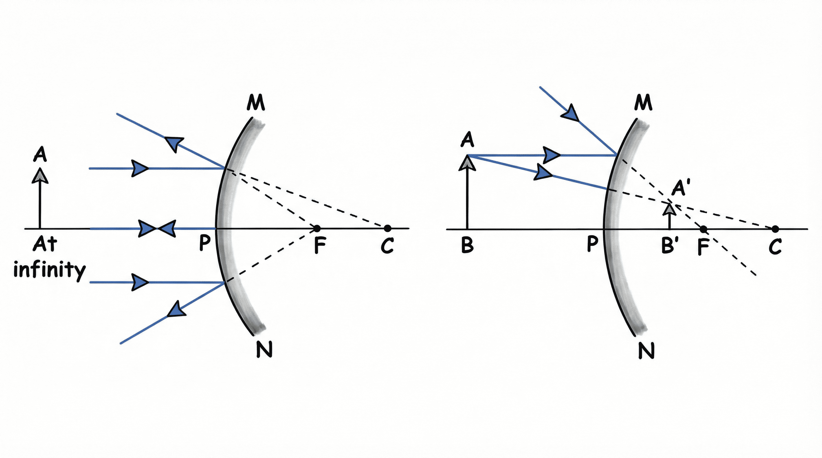 Figure 1.3: Image Formation by Convex Mirror
Convex mirror always forms a Virtual, Erect, and Diminished image � regardless of object position.
This is why they are used as rear-view mirrors.
MIRROR FORMULA
$$ \frac{1}{v} + \frac{1}{u} = \frac{1}{f} \quad \text{also: } f = \frac{R}{2} $$
$$ m = -\frac{v}{u} = \frac{h'}{h} $$
If m is (−) → Image is Real & Inverted.
If m is (+) → Image is Virtual & Erect.
2. Refraction of Light
Refraction is the bending of light when it passes from one transparent medium to another,
due to the change in its speed.
Laws of Refraction (Snell's Law)
- The incident ray, the refracted ray, and the normal at the point of incidence all lie in the
same plane.
- Snell's Law: The ratio of sin of angle of incidence to sin of angle of refraction
is constant for a given pair of media:
$$ \frac{\sin i}{\sin r} = n_{21} = \text{constant} $$
Refractive Index (n) � Absolute:
$$ n_m = \frac{c}{v} = \frac{\text{Speed in vacuum}}{\text{Speed in medium}} $$
Key values: Water = 1.33 | Glass = 1.5 | Diamond = 2.42
Higher n → optically denser → light bends more → more "brilliant".
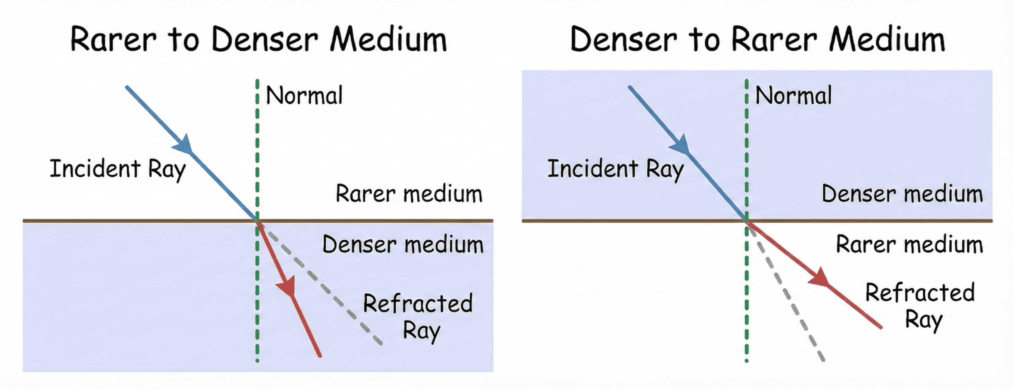 Figure 1.4a: Light Bending � Rarer to Denser & Denser to Rarer
Direction of Bending:
• Rarer to Denser (e.g., air to glass): Speed decreases → bends
towards normal (∠r < ∠i).
• Denser to Rarer (e.g., glass to air): Speed increases → bends
away from normal (∠r > ∠i).
Refraction through a Glass Slab & Lateral Displacement
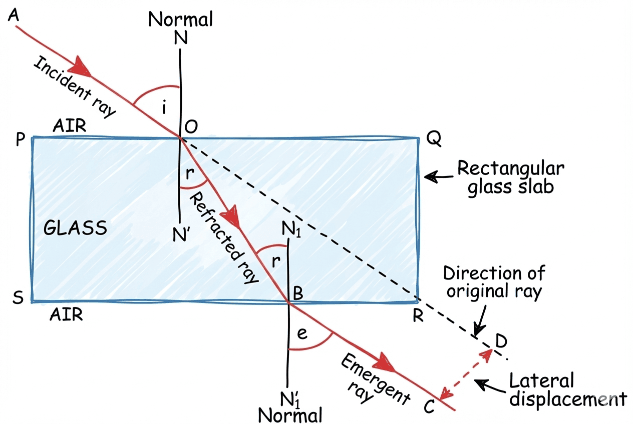 Figure 1.4b: Refraction through a Glass Slab
When light passes through a glass slab (two parallel faces), the emergent ray is
parallel to the incident ray but is shifted sideways. This perpendicular shift is
called Lateral Displacement.
It increases with: (1) Greater thickness of slab (2) Higher refractive index (3) Larger
angle of incidence.
3. Lenses
| Lens |
Type |
Focal Length (f) |
Power (P) |
Use |
| Convex |
Converging |
Positive (+) |
Positive (+) |
Magnifying glass, camera, spectacles for hypermetropia |
| Concave |
Diverging |
Negative (−) |
Negative (−) |
Spectacles for myopia, peepholes |
Rules for Ray Tracing (Lenses)
- Rule 1: A ray parallel to Principal Axis → after refraction, passes through
F2 (Convex) or appears to come from F2 (Concave).
- Rule 2: A ray through Optical Centre (O) → goes undeviated
(straight through without bending).
- Rule 3: A ray through F1 (Convex) or directed towards F1
(Concave) → emerges parallel to Principal Axis.
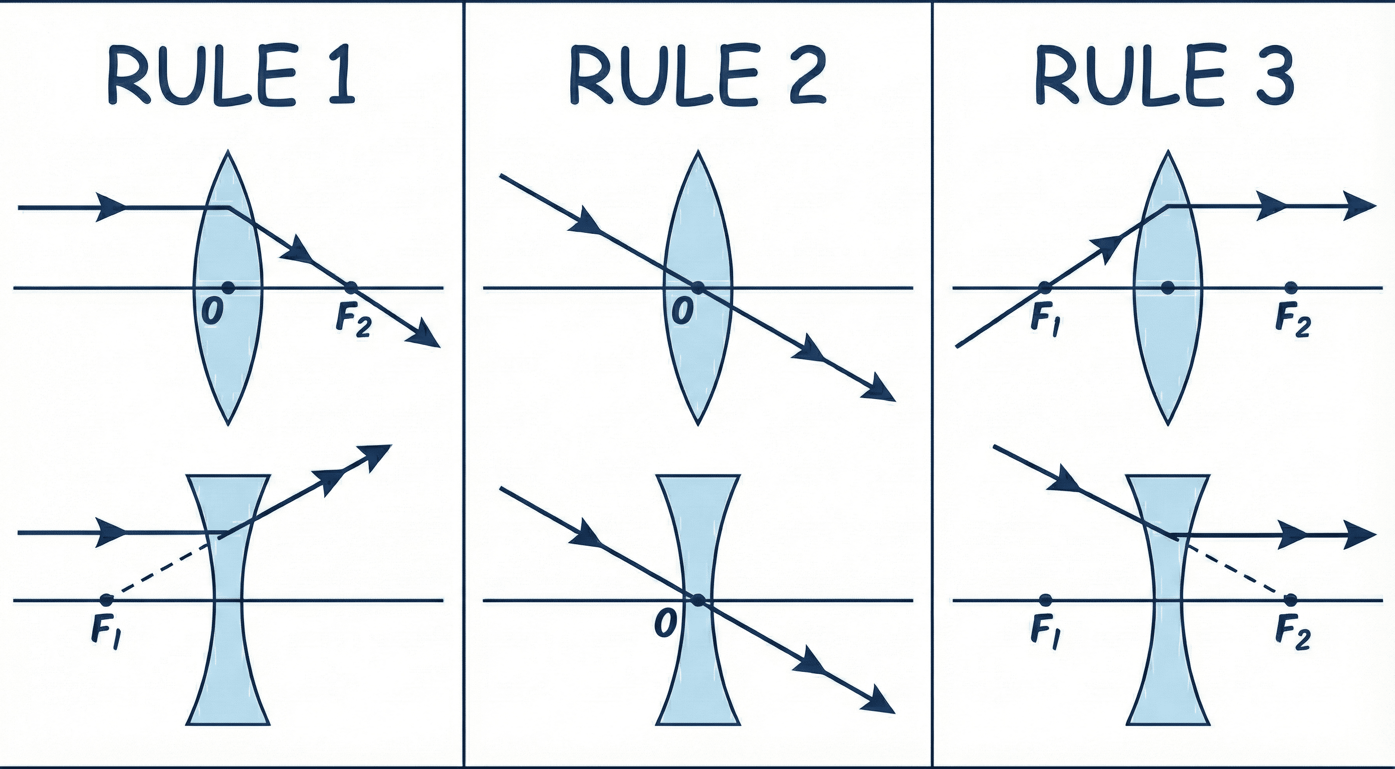 Figure 1.5a: Rules for Ray Tracing (Lenses)
Image Formation by Convex Lens
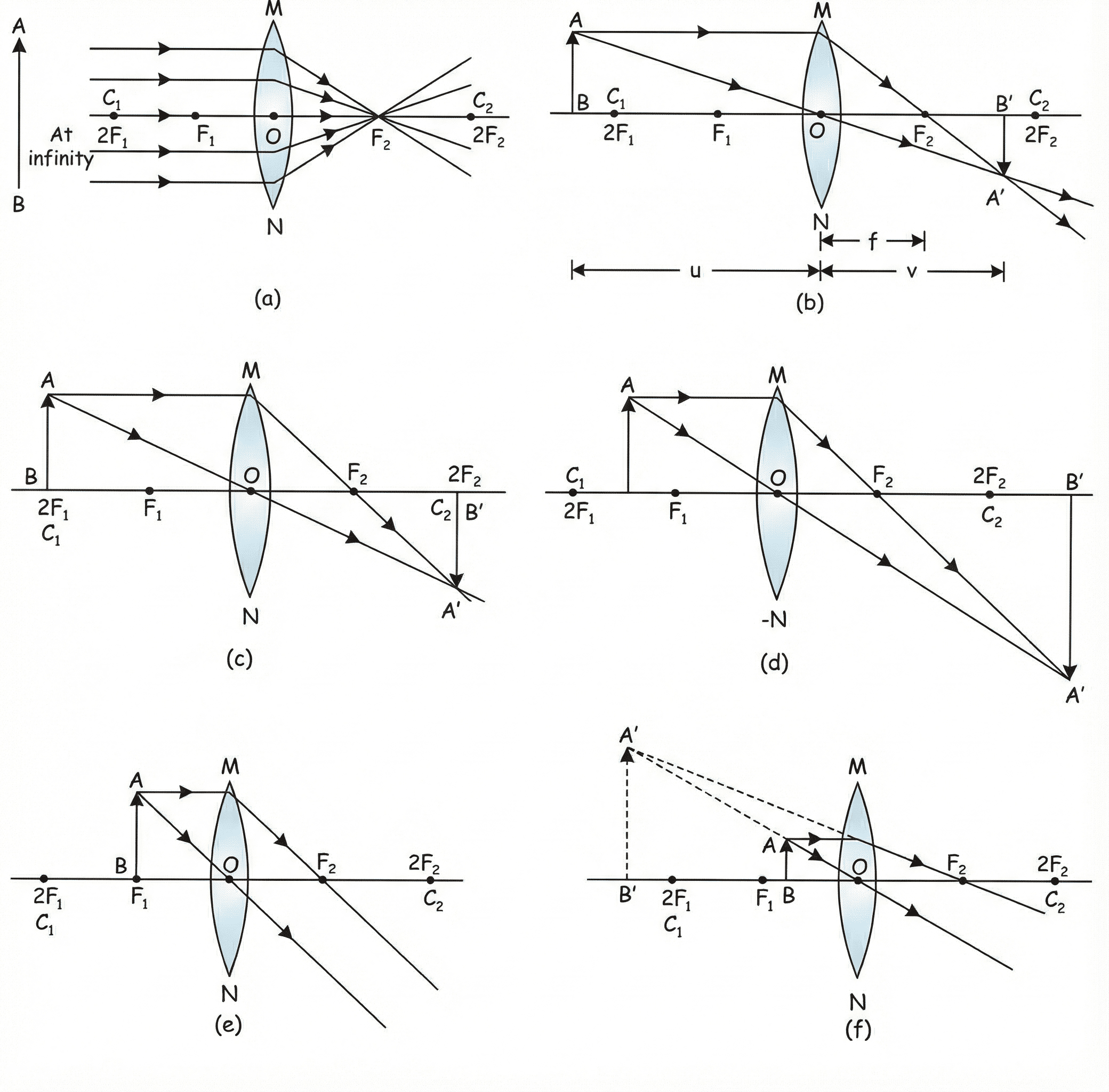 Figure 1.5b: Image Formation by Convex Lens
| Object Position |
Image Position |
Size |
Nature |
| At Infinity |
At Focus F2 |
Highly Diminished |
Real & Inverted |
| Beyond 2F1 |
Between F2 and 2F2 |
Diminished |
Real & Inverted |
| At 2F1 |
At 2F2 |
Same Size |
Real & Inverted |
| Between F1 and 2F1 |
Beyond 2F2 |
Enlarged |
Real & Inverted |
| At Focus F1 |
At Infinity |
Highly Enlarged |
Real & Inverted |
| Between F1 and O |
Same side as object |
Enlarged |
Virtual & Erect |
Image Formation by Concave Lens
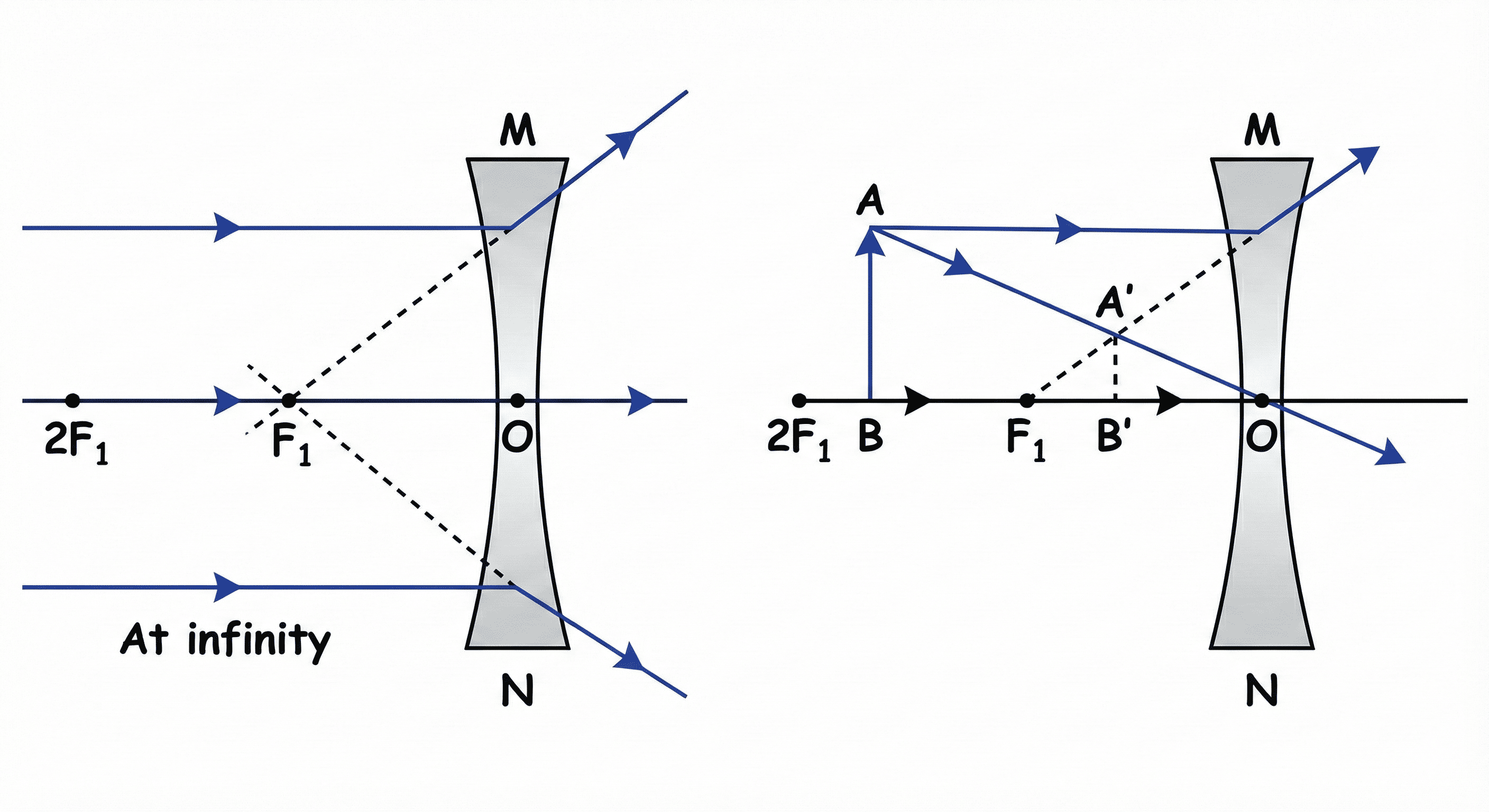 Figure 1.6: Image Formation by Concave Lens
| Object Position |
Image Position |
Size |
Nature |
| At Infinity |
At Focus F1 (same side) |
Highly Diminished |
Virtual & Erect |
| Between Infinity & O |
Between F1 and O (same side) |
Diminished |
Virtual & Erect |
LENS FORMULA
$$ \frac{1}{v} - \frac{1}{u} = \frac{1}{f} $$
$$ m = \frac{v}{u} \quad (\text{Note: positive sign, unlike mirror}) $$
$$ P = \frac{1}{f(\text{in metres})} \text{ Dioptre (D)} $$
Power of combined lenses: Pnet = P1 + P2 + P3 (algebraic
sum)
Mirror: 1/v + 1/u = 1/f | m = −v/u
Lens: 1/v − 1/u = 1/f | m = +v/u
The sign difference in both the formula and magnification is the most common exam trap!
