Physics Master Notes (2025-26)
Created by Team Vardaan with ❤️
UNIT 1: LIGHT – REFLECTION & REFRACTION
1. Reflection of Light
Laws of Reflection:
- Angle of Incidence = Angle of Reflection (∠i = ∠r).
- The Incident ray, the Reflected ray, and the Normal all lie in the same plane.
2. Spherical Mirrors (Concave & Convex)
Uses (Most Asked):
1. Concave: Shaving mirrors (enlarged image), Torches/Headlights (parallel beam), Solar furnaces (concentrate heat), Dentists.
2. Convex: Rear-view mirrors (Wider field of view + Always erect image).
1. Concave: Shaving mirrors (enlarged image), Torches/Headlights (parallel beam), Solar furnaces (concentrate heat), Dentists.
2. Convex: Rear-view mirrors (Wider field of view + Always erect image).
A. Key Terms (Mirrors & Lenses)
- Pole (P) / Optical Centre (O): The geometric center of the spherical mirror/lens.
- Centre of Curvature (C): The center of the hollow glass sphere of which the mirror/lens is a part.
- Principal Axis: The straight line passing through the Pole (P) and Center of Curvature (C).
- Principal Focus (F): The point on the principal axis where light rays parallel to the axis converge (Concave Mirror/Convex Lens) or appear to diverge from (Convex Mirror/Concave Lens).
- Focal Length (f): The distance between the Pole (P) and the Principal Focus (F).
- Aperture: The diameter of the reflecting surface or the lens.
%20&%20Convex%20Lens%20(Right).png) Figure 1.0: Key Terms - Concave Mirror (Left) & Convex Lens (Right)
Figure 1.0: Key Terms - Concave Mirror (Left) & Convex Lens (Right)
Relation: Radius of Curvature (R) = 2 × Focal Length (f)
B. Rules for Image Formation (Mirrors)
- Rule 1: A ray parallel to Principal Axis passes through Focus (F) after reflection.
- Rule 2: A ray passing through Focus (F) becomes parallel to Principal Axis.
- Rule 3: A ray passing through Center of Curvature (C) retraces its path.
- Rule 4: A ray incident obliquely at the Pole (P) reflects with equal angle (∠i = ∠r).
.png) Figure 1.0b: Rules for Ray Tracing (Mirrors)
Figure 1.0b: Rules for Ray Tracing (Mirrors)
C. Image Formation by Spherical Mirrors & Lenses
.png) Figure 1.1: Ray Diagrams for Concave Mirror
Figure 1.1: Ray Diagrams for Concave Mirror
| Image formation by concave mirror | |||
|---|---|---|---|
| Object Position | Image Position | Size | Nature |
| At Infinity | At Focus F | Highly Diminished | Real & Inverted |
| Beyond C | Between F and C | Diminished | Real & Inverted |
| At C | At C | Same Size | Real & Inverted |
| Between C and F | Beyond C | Enlarged | Real & Inverted |
| At F | At Infinity | Highly Enlarged | Real & Inverted |
| Between P and F | Behind the Mirror | Enlarged | Virtual & Erect |
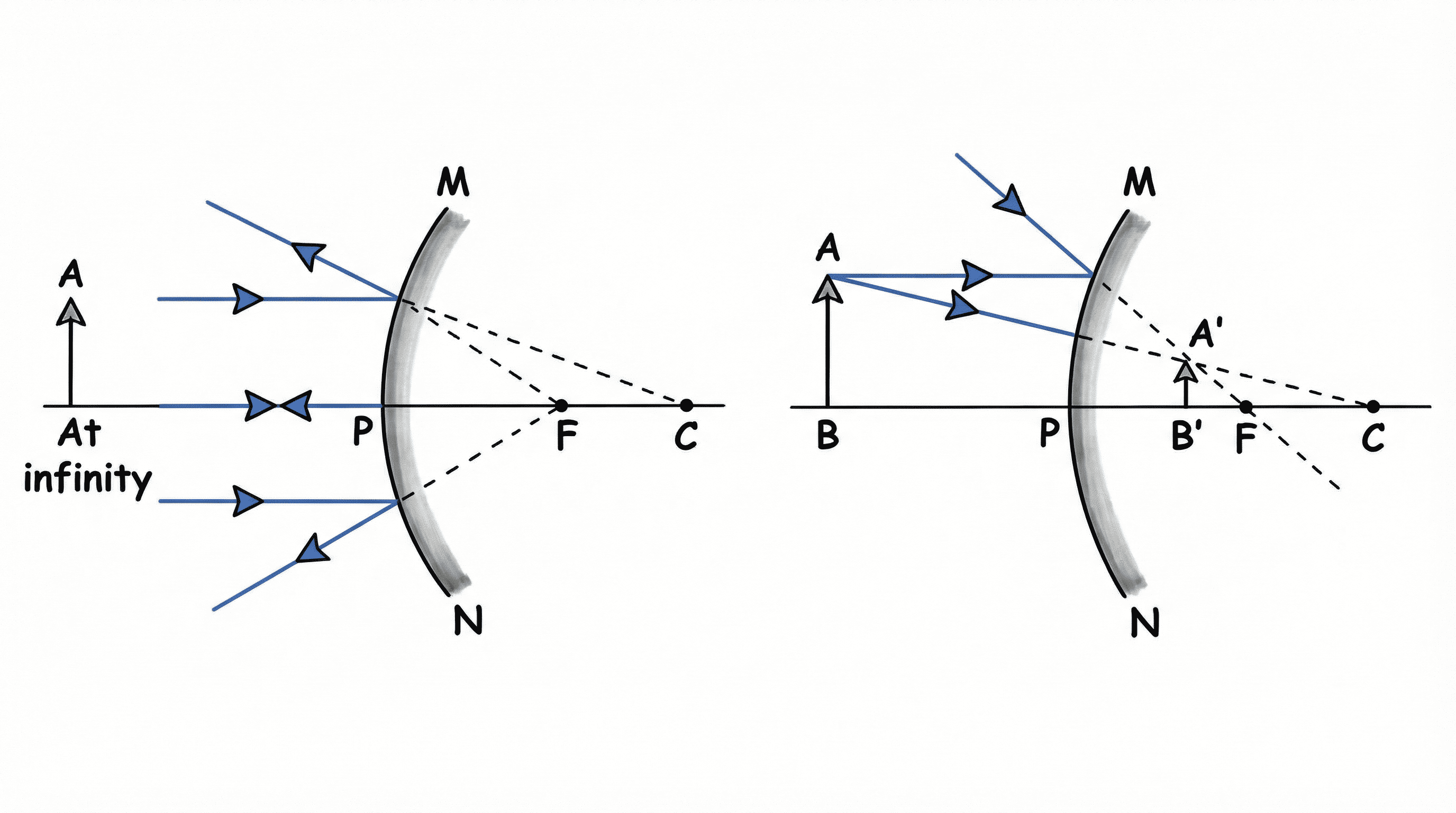 Figure 1.2: Ray Diagrams for Convex Mirror
| Image formation by convex mirror | |||
|---|---|---|---|
| Object Position | Image Position | Size | Nature |
| At Infinity | At Focus F (Behind) | Highly Diminished | Virtual & Erect |
| Between Infinity & Pole | Between P and F (Behind) | Diminished | Virtual & Erect |
3. Mirror Formula & Magnification
Mirror Formula:
1v + 1u = 1f
1v + 1u = 1f
Magnification (m):
m = h'h = - vu
m = h'h = - vu
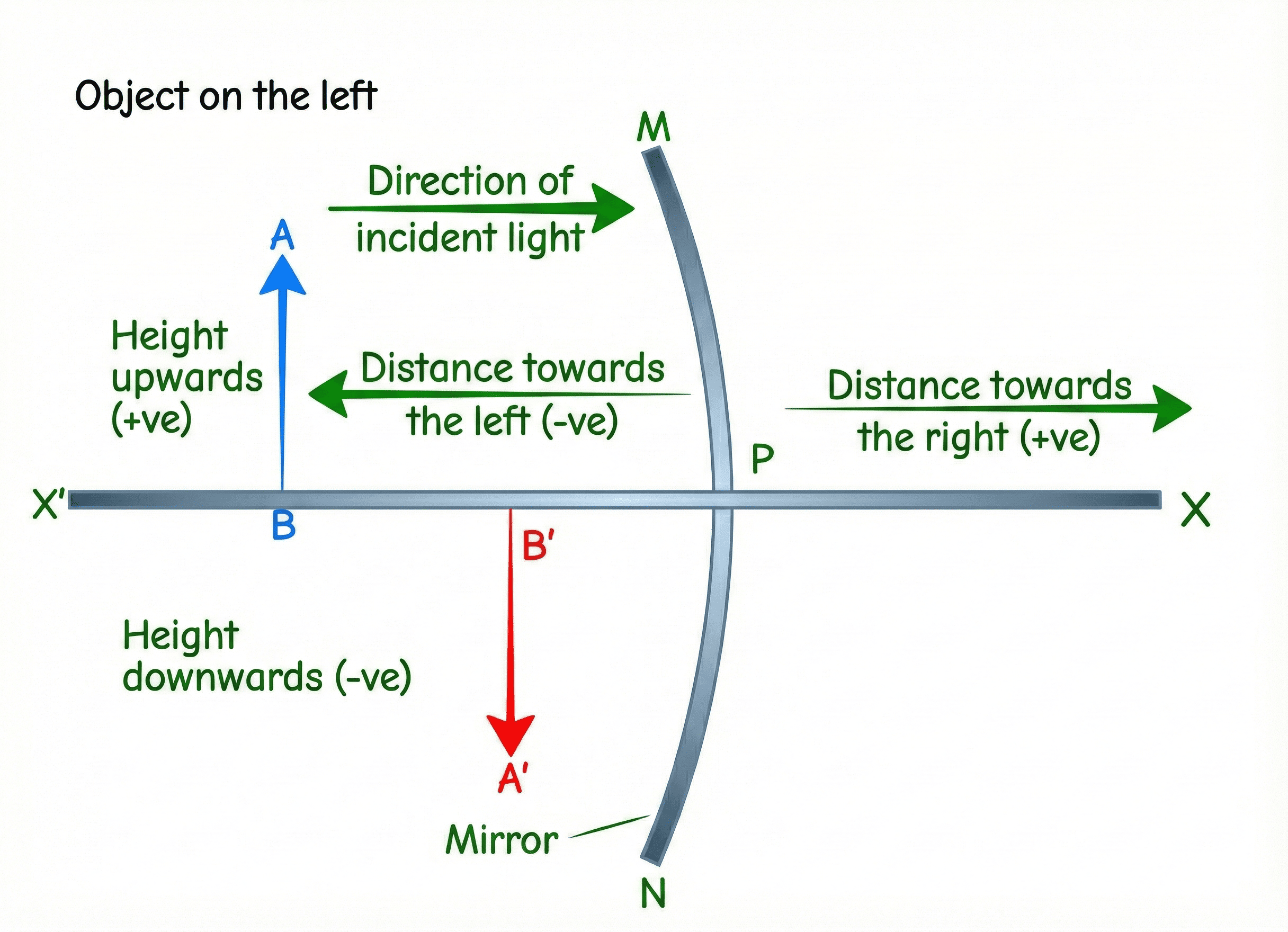
Sign Convention Hack:
- u (Object dist): ALWAYS Negative (-).
- f (Focal Length): Concave = (-); Convex = (+).
- m (Magnification): (-) = Real/Inverted; (+) = Virtual/Erect.
4. Refraction of Light
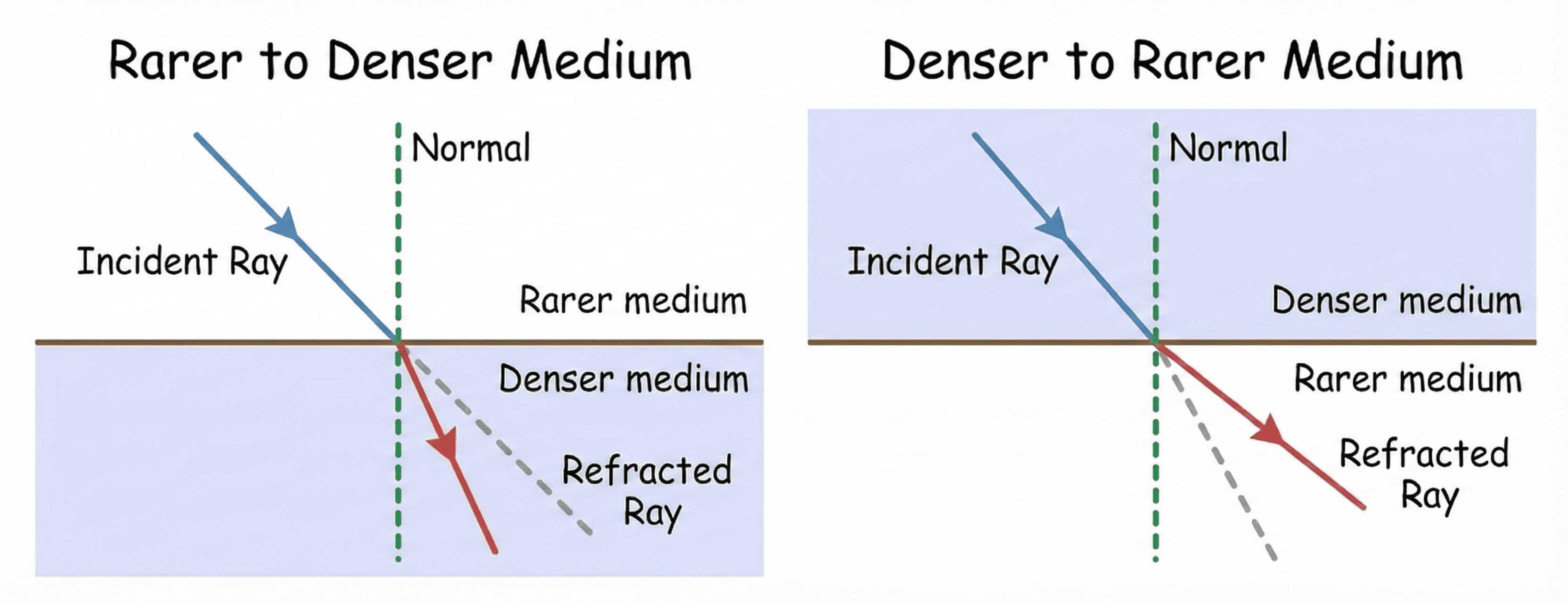 Figure 1.3: Refraction Rules
Snell's Law: sin isin r = constant (n)
Absolute Refractive Index (nm): nm = c (Speed in air)v (Speed in medium)
Absolute Refractive Index (nm): nm = c (Speed in air)v (Speed in medium)
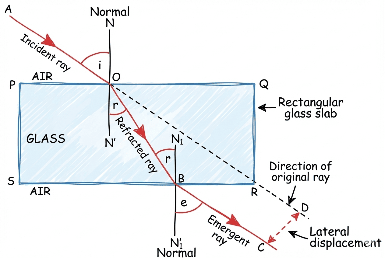 Figure 1.4: Refraction through Glass Slab
5. Lenses: Diagrams & Formulas
A. Rules for Image Formation (Lenses)
- Rule 1: A ray parallel to Principal Axis passes through Principal Focus (F).
- Rule 2: A ray passing through the Optical Centre (O) goes undeviated (straight).
- Rule 3: A ray passing through Principal Focus (F) becomes parallel to Principal Axis.
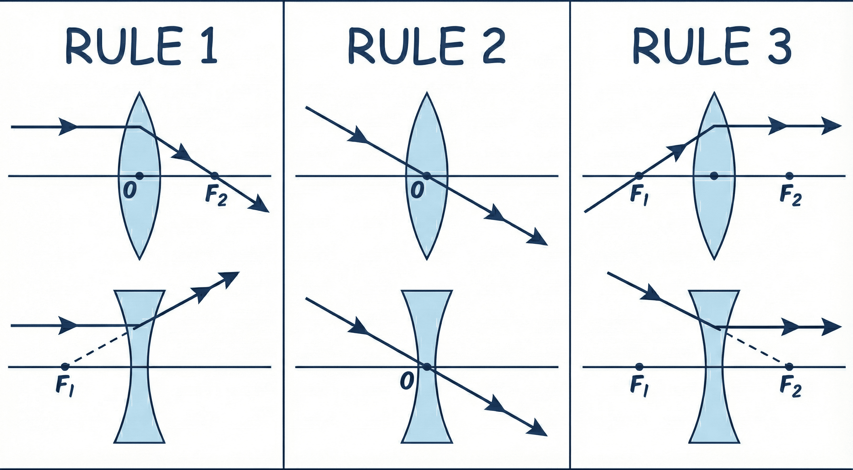 Figure 1.5a: Rules for Ray Tracing (Lenses)
B. Ray Diagrams Checklist
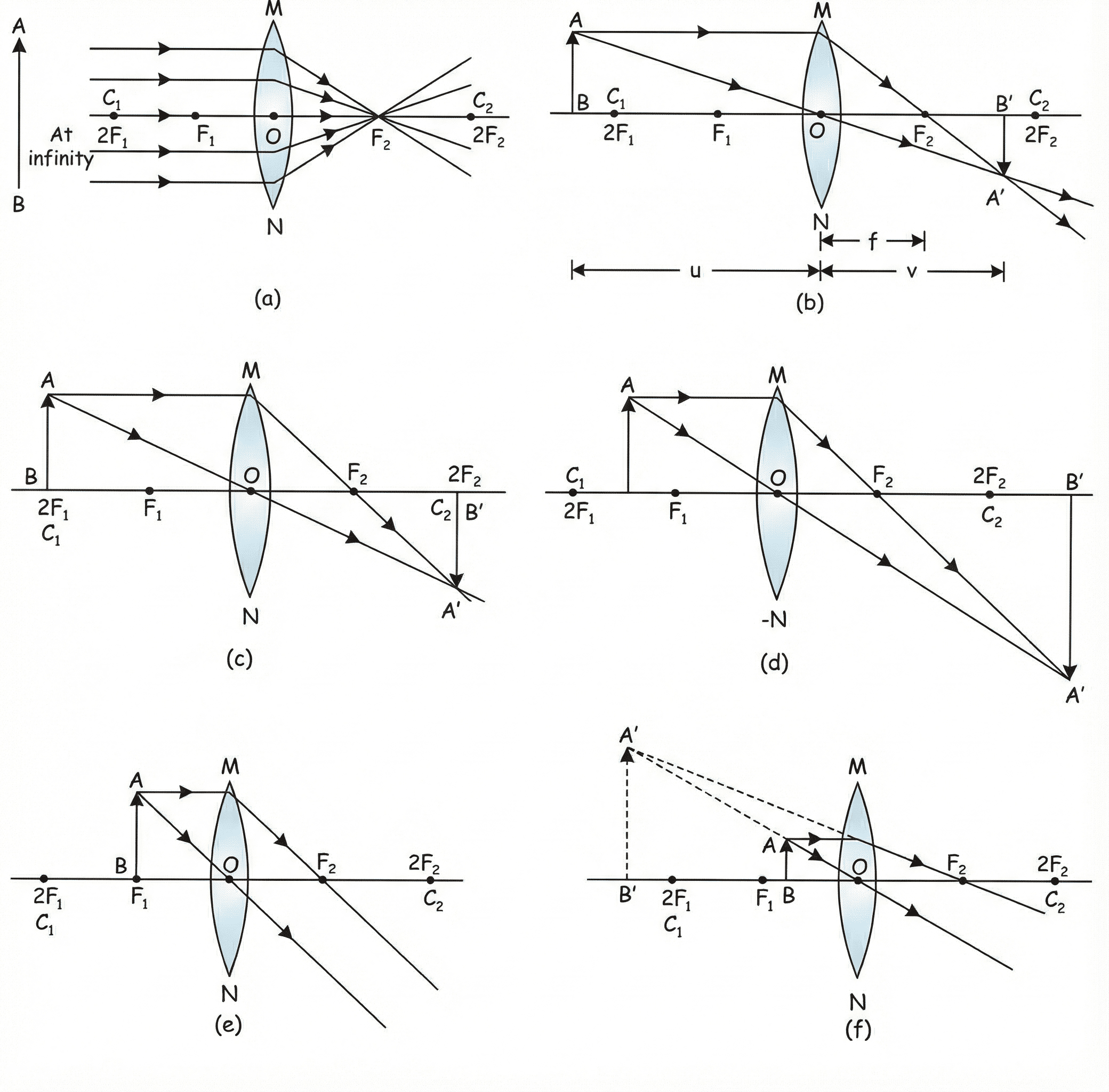 Figure 1.5b: Ray Diagrams for Convex Lens
| Image formation by convex lens | |||
|---|---|---|---|
| Object Position | Image Position | Size | Nature |
| At Infinity | At Focus F2 | Highly Diminished | Real & Inverted |
| Beyond 2F1 | Between F2 and 2F2 | Diminished | Real & Inverted |
| At 2F1 | At 2F2 | Same Size | Real & Inverted |
| Between F1 and 2F1 | Beyond 2F2 | Enlarged | Real & Inverted |
| At Focus F1 | At Infinity | Highly Enlarged | Real & Inverted |
| Between F1 and O | On same side as object | Enlarged | Virtual & Erect |
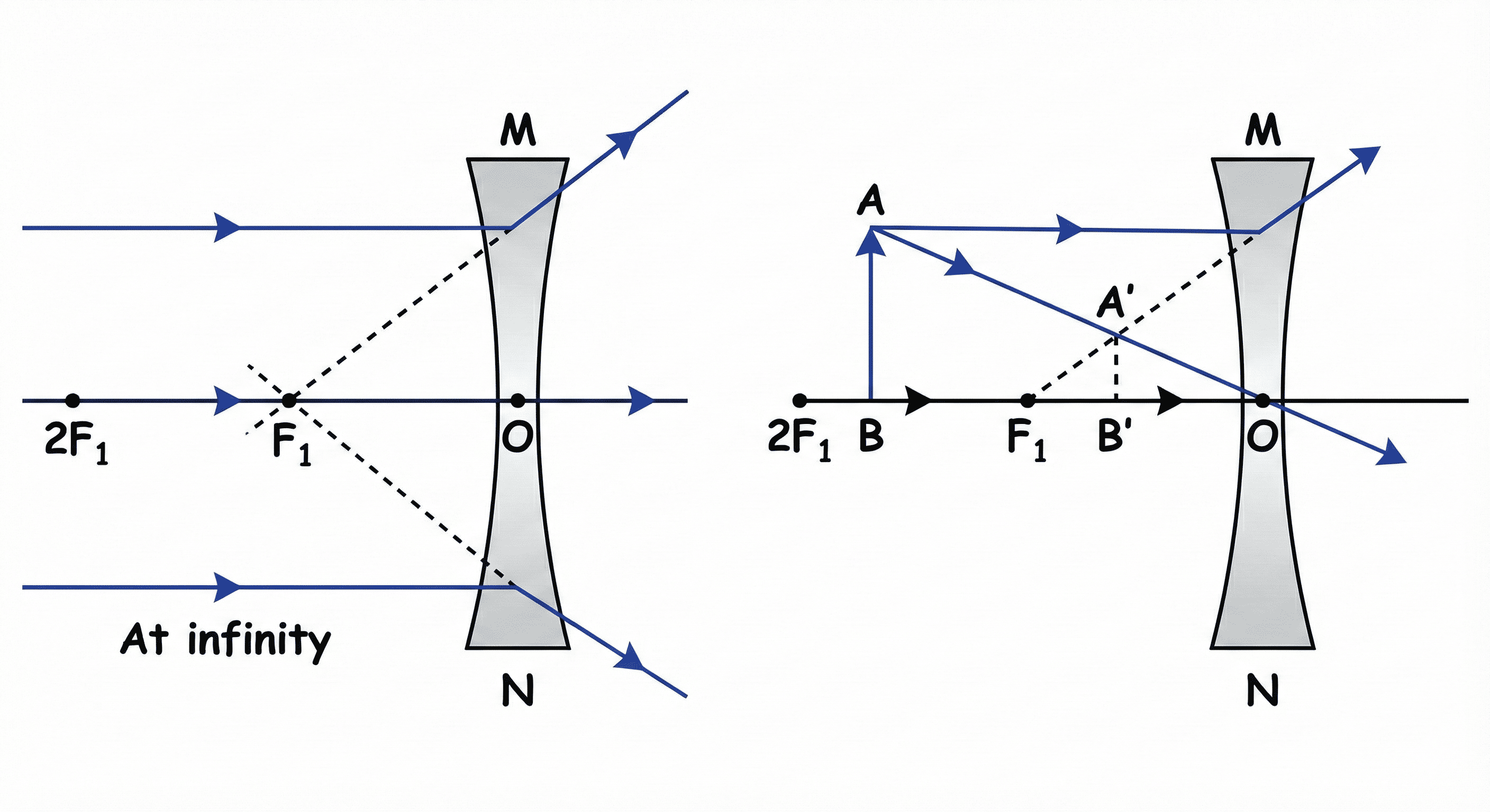 Figure 1.6: Ray Diagrams for Concave Lens
| Image formation by concave lens | |||
|---|---|---|---|
| Object Position | Image Position | Size | Nature |
| At Infinity | At Focus F1 | Highly Diminished | Virtual & Erect |
| Between Infinity & O | Between F1 and O | Diminished | Virtual & Erect |
Lens Formula:
1v -
1u =
1f
Magnification (Lens): m = vu (Note: Positive sign)
Power (P): P = 1f (in Meters!) (Unit: Dioptre D)
Magnification (Lens): m = vu (Note: Positive sign)
Power (P): P = 1f (in Meters!) (Unit: Dioptre D)
UNIT 2: HUMAN EYE & COLOURFUL WORLD
1. Structure of the Eye
| Part | Function |
|---|---|
| Cornea | Front bulging part. Most refraction happens here. |
| Iris | Controls pupil size (Dark muscular diaphragm). |
| Pupil | Regulates amount of light entering. |
| Ciliary Muscles | Adjusts lens curvature (Power of Accommodation). |
| Retina | Screen with light-sensitive cells. |
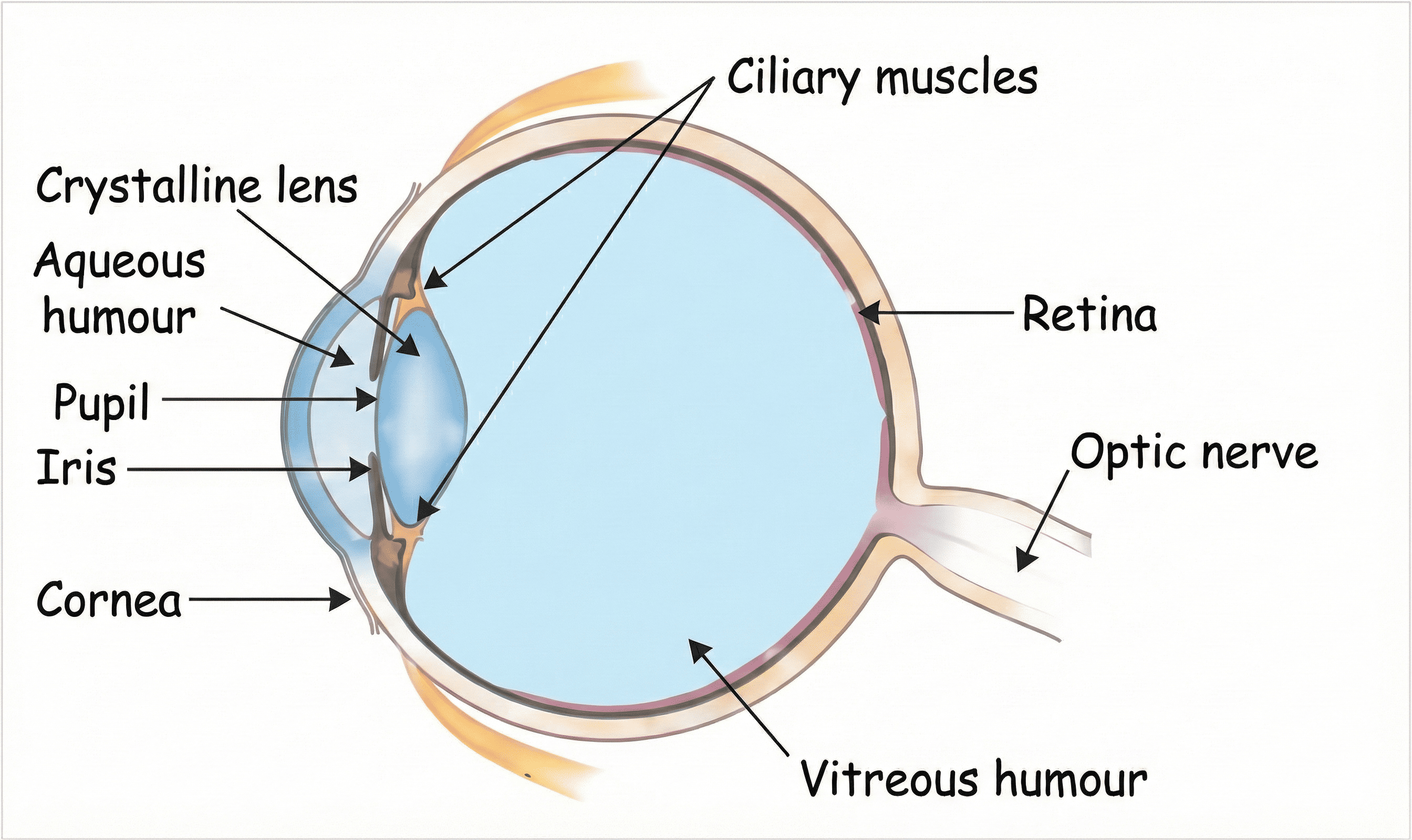 Figure 2.0: Structure of the Human Eye
2. Defects of Vision (Quick Theory Table)
| Defect | Definition & Image Position | Causes | Correction |
|---|---|---|---|
| Myopia (Near-sightedness) |
Can see near objects clearly; distant objects blurry. Image forms in front of retina. |
1. Excessive curvature of eye lens. 2. Elongation of eyeball. |
Concave Lens |
| Hypermetropia (Far-sightedness) |
Can see distant objects clearly; near objects blurry. Image forms behind the retina. |
1. Focal length of eye lens is too long. 2. Eyeball is too small. |
Convex Lens |
| Presbyopia (Old age Hypermetropia) |
Power of accommodation decreases with ageing. Near point recedes. | 1. Weakening of ciliary muscles. 2. Diminishing flexibility of lens. |
Bi-focal Lens (Concave top, Convex bottom) |
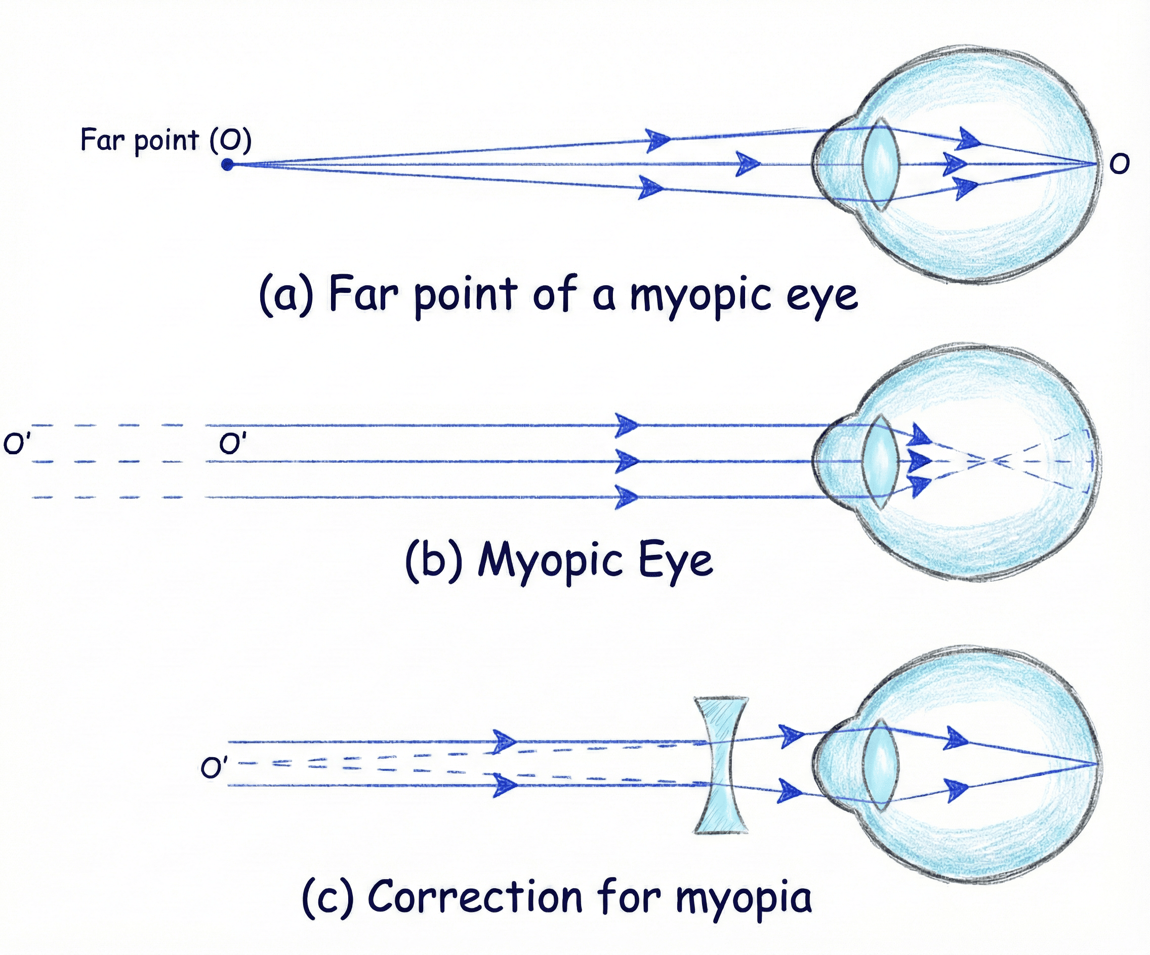 Figure 2.1: Myopia (Defect and Correction)
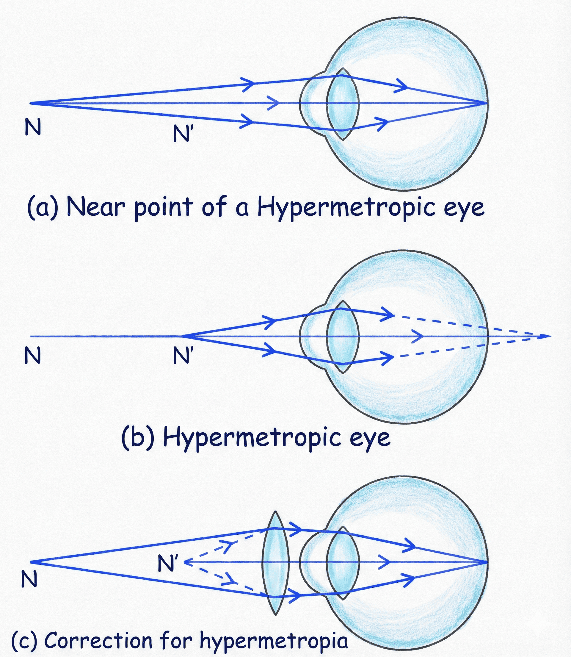 Figure 2.2: Hypermetropia (Defect and Correction)
3. Prism & Light Phenomena
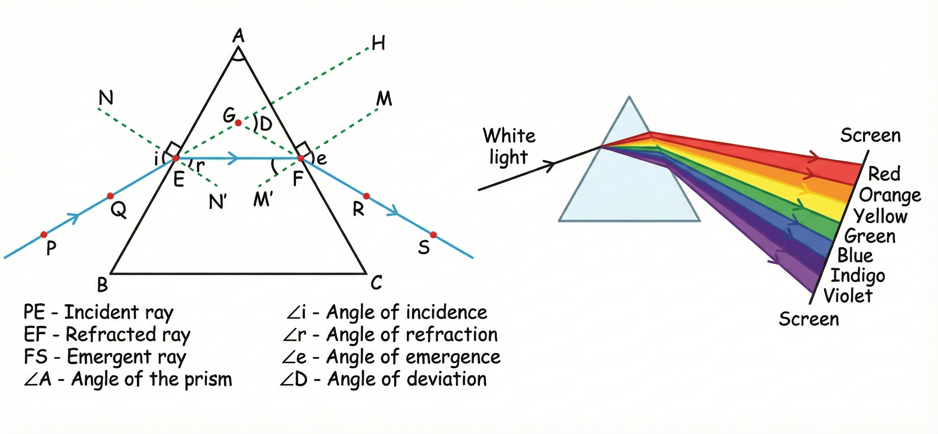 Figure 2.3: Dispersion of White Light by Glass Prism
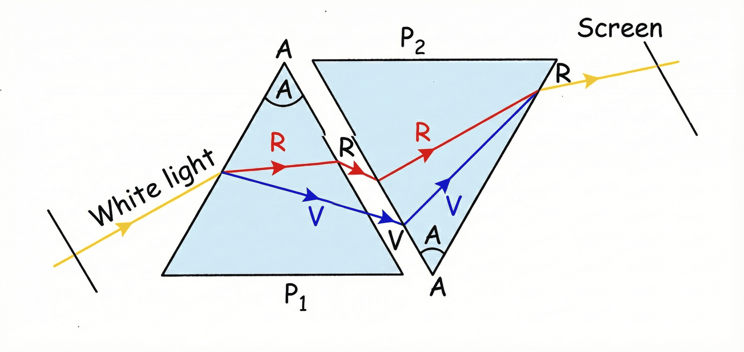 Figure 2.4: Recombination of Spectrum
Rainbow Formation (From NCERT)
A rainbow is a natural spectrum appearing in the sky after a rain shower. It is caused by dispersion of sunlight by tiny water droplets, present in the atmosphere. A rainbow is always formed in a direction opposite to that of the Sun.
- Mechanism: The water droplets act like small prisms.
- 3-Step Process:
- They refract and disperse the incident sunlight.
- Then they reflect it internally (Internal Reflection).
- Finally, they refract it again when it comes out of the raindrop.
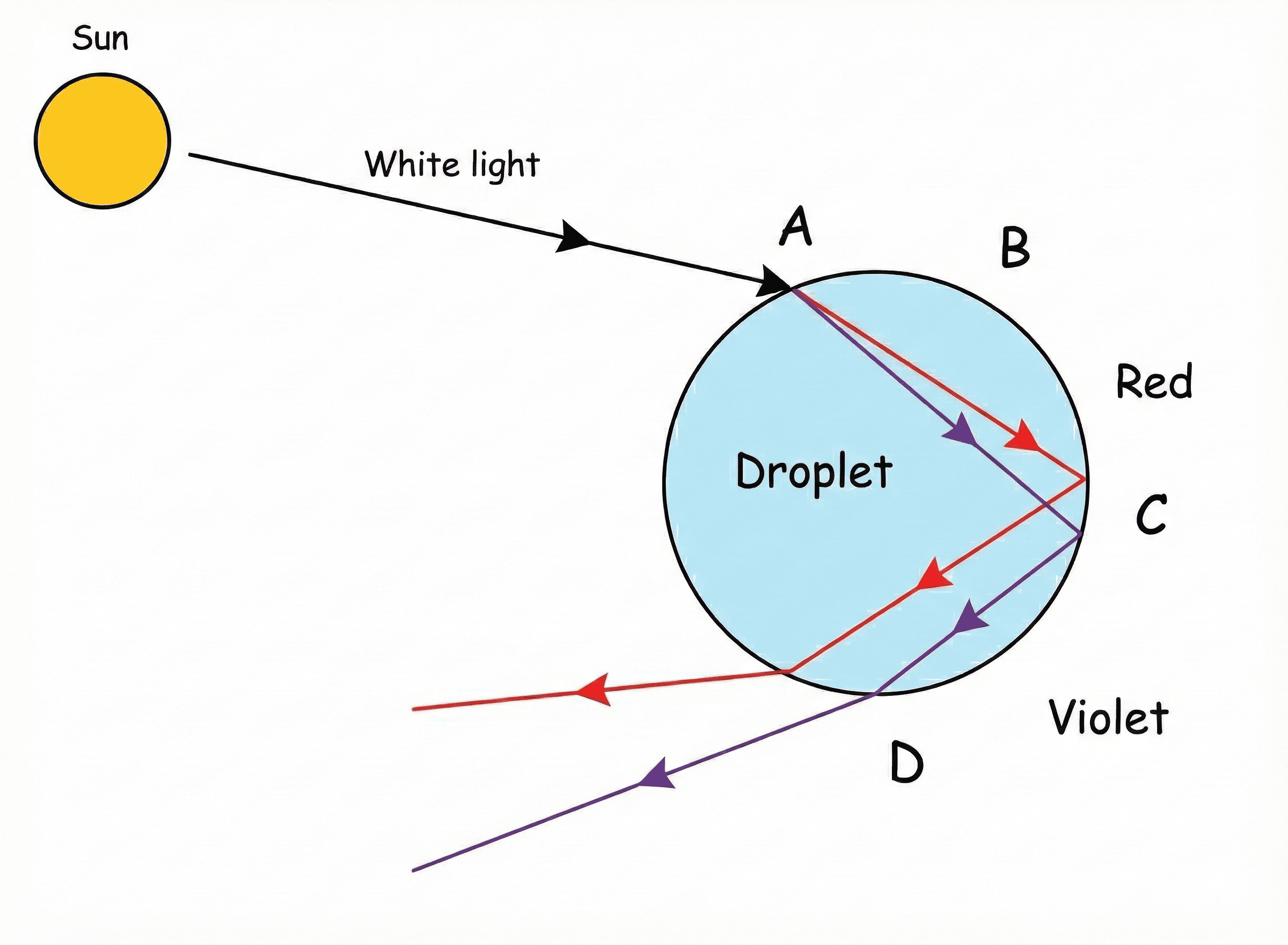 Figure 2.5: Rainbow Formation
4. Atmospheric Refraction
Definition: Refraction of light caused by different layers of the atmosphere having varying optical densities (hot air is rarer, cold air is denser).
- Twinkling of Stars:
• Stars are distant point-sized sources of light.
• As starlight enters the atmosphere, it undergoes refraction continuously due to changing air density.
• The apparent position of the star fluctuates, and the amount of light entering the eye flickers. - Why Planets Don't Twinkle:
• Planets are closer and appear as extended sources (collection of many point sources).
• Changes in light from different points cancel each other out. Net variation is zero. - Advanced Sunrise & Delayed Sunset:
• The Sun is visible 2 minutes before actual sunrise and 2 minutes after actual sunset.
• Reason: Light bends near the horizon due to atmospheric refraction, making the Sun appear higher than it effectively is.
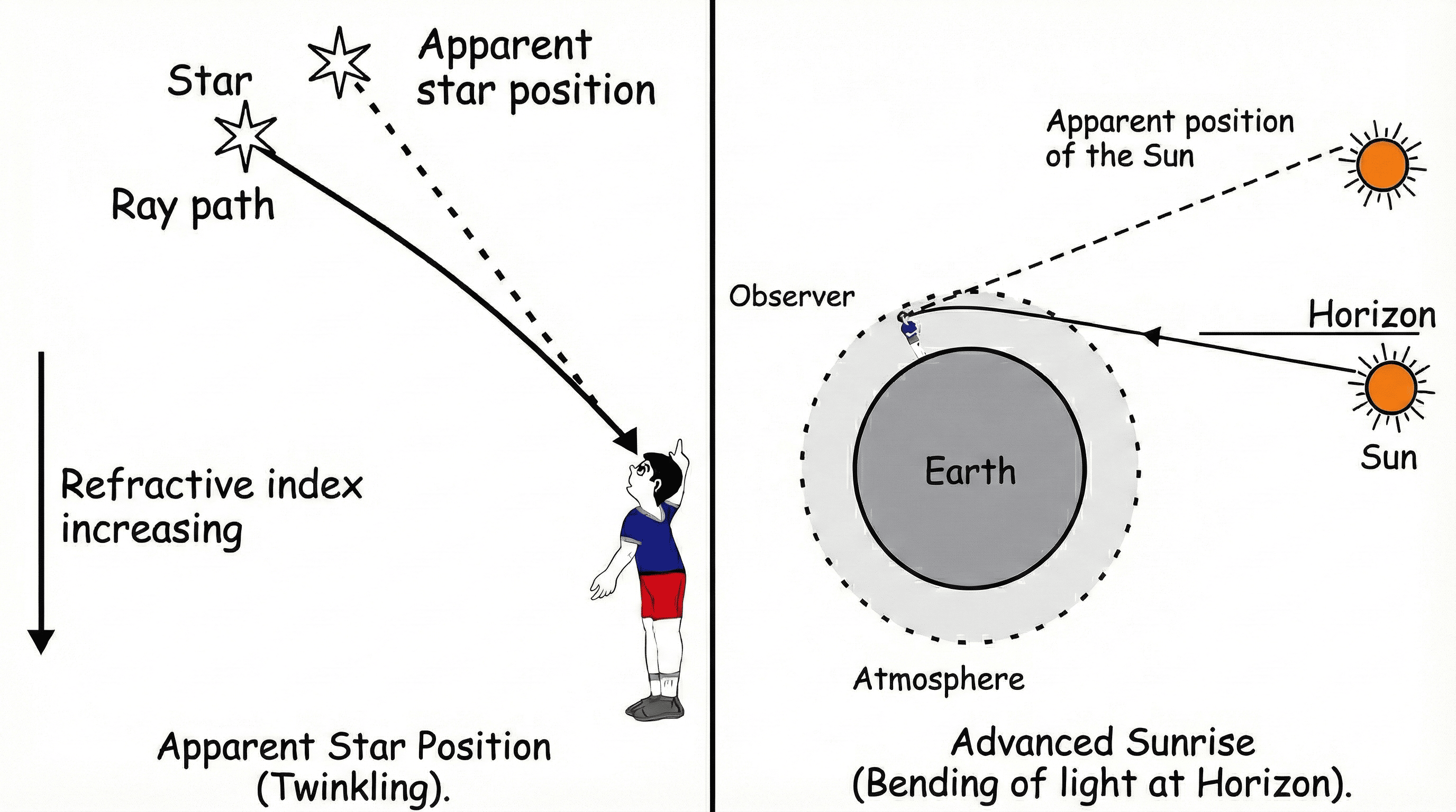 Figure 2.6: Atmospheric Refraction Phenomena
5. Scattering of Light
- Tyndall Effect: The phenomenon of scattering of light by colloidal particles (e.g., sunlight passing through a dense forest canopy or smoke-filled room). The path of the beam becomes visible.
- Why Sky is Blue:
• Air molecules and fine particles are smaller than the wavelength of visible light.
• They scatter shorter wavelengths (Blue/Violet) more strongly than long wavelengths (Red).
• The scattered blue light enters our eyes. (Note: We see blue instead of violet because our eyes are more sensitive to blue).
Natural Phenomena Reasoning Summary:
1. Stars Twinkle: Point source + Changing atmospheric density.
2. Planets Don't Twinkle: Extended source + Variations cancel out.
3. Blue Sky: Scattering of blue light by fine air particles.
4. Danger Signals Red: Red has longest Wavelength (λ), scattered least by fog/smoke.
1. Stars Twinkle: Point source + Changing atmospheric density.
2. Planets Don't Twinkle: Extended source + Variations cancel out.
3. Blue Sky: Scattering of blue light by fine air particles.
4. Danger Signals Red: Red has longest Wavelength (λ), scattered least by fog/smoke.
UNIT 3: ELECTRICITY
1. Basics & Definitions
- Electric Current (I): Rate of flow of charge. I = Q/t.
1 Ampere: Flow of 1 Coulomb charge per 1 Second. - Potential Difference (V): Work done to move unit charge. V = W/Q.
1 Volt: 1 Joule work done to move 1 Coulomb charge. - Charge on 1 Electron (e): 1.6 × 10⁻¹⁹ C.
2. Circuit Diagram Symbols
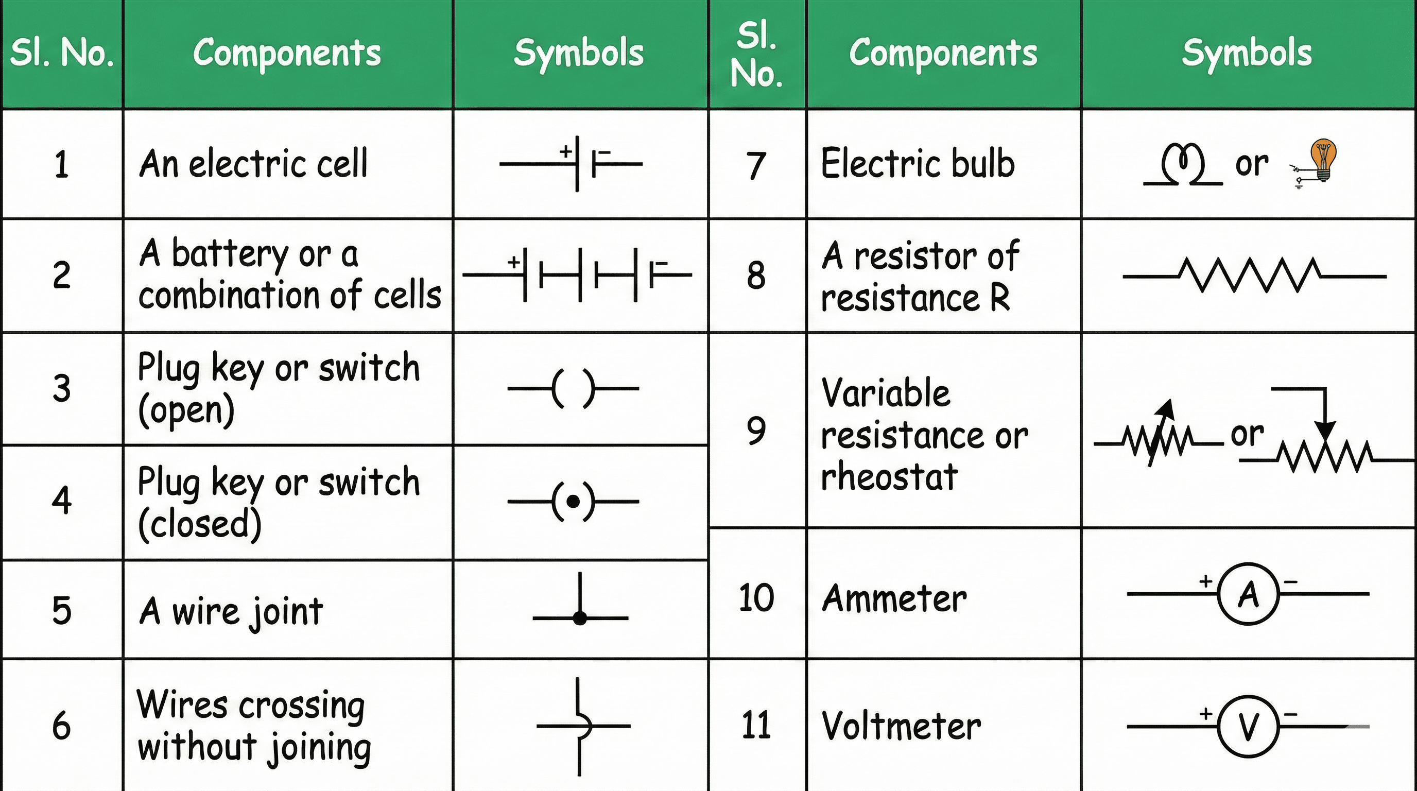 Figure 3.1: Standard Circuit Symbols
3. Ohm's Law & Resistance
A. Verification of Ohm's Law (Experiment)
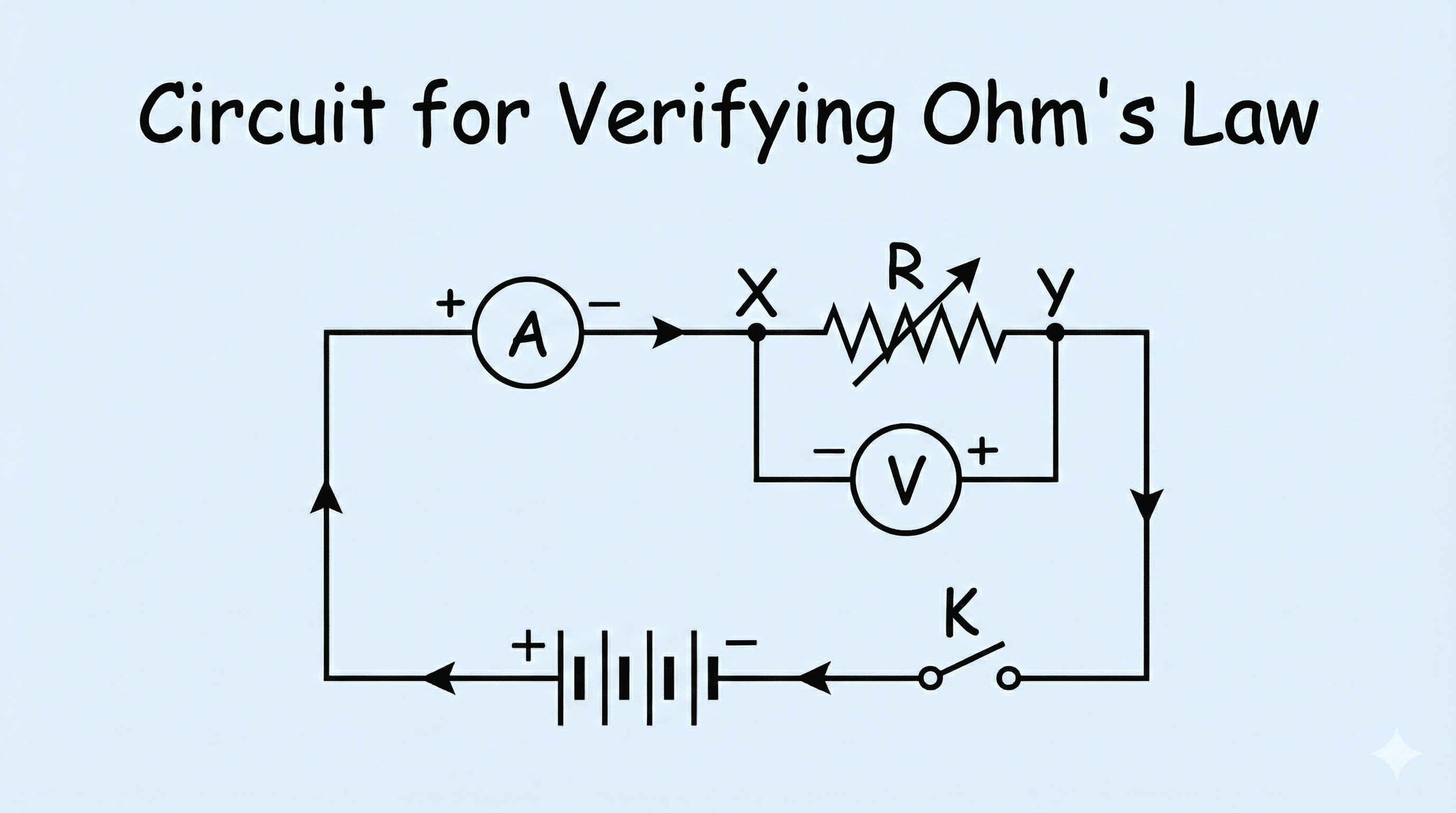 Figure 3.2: Circuit for Ohm's Law
- Aim: To verify V ∝ I for a resistor.
- Setup: Connect Resistor, Ammeter (Series), Voltmeter (Parallel), Battery, and Rheostat.
- Procedure: Vary current using Rheostat. Note V and I readings. Calculate V/I ratio (It remains constant).
- Observation: V-I Graph is a straight line passing through origin.
B. Graphs (V-I vs I-V)
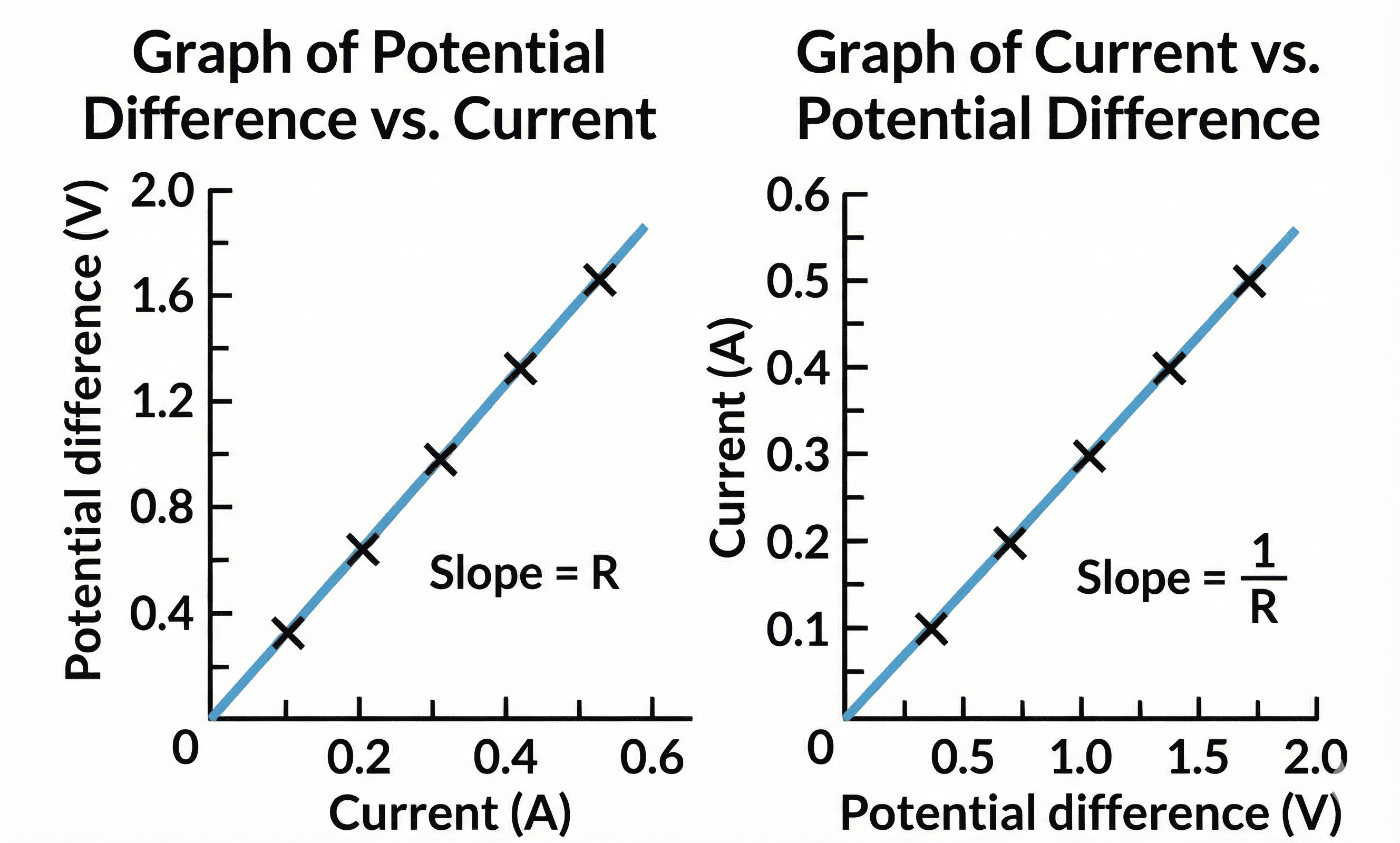 Figure 3.3: V-I Graph for Ohmic Conductor
Important Note on Graphs:
• V-I Graph: Slope = Resistance (R).
• I-V Graph: Slope = 1/Resistance (1/R). (No image required, just remember this relation).
• V-I Graph: Slope = Resistance (R).
• I-V Graph: Slope = 1/Resistance (1/R). (No image required, just remember this relation).
V = IR (at const. Temp)
Resistance Factors: R = ρ LA
1. Directly proportional to Length (L).
2. Inversely proportional to Area (A).
3. Depends on Nature of Material (ρ) & Temperature.
Resistance Factors: R = ρ LA
1. Directly proportional to Length (L).
2. Inversely proportional to Area (A).
3. Depends on Nature of Material (ρ) & Temperature.
Conceptual Trap:
If wire is stretched to double length:
Length becomes 2L, Area becomes A/2.
New Resistance R' = 4 times the original R.
If wire is stretched to double length:
Length becomes 2L, Area becomes A/2.
New Resistance R' = 4 times the original R.
4. Series vs Parallel
| Series | Parallel |
|---|---|
| Current (I) same. | Voltage (V) same. |
| Req = R1 + R2 | 1/Req = 1/R1 + 1/R2 |
 Figure 3.4: Series and Parallel Circuits
5. Heating Effect & Power (Expanded)
A. Joule's Law of Heating
Heat produced in a resistor is:
- Directly proportional to square of current (H ∝ I2).
- Directly proportional to resistance (H ∝ R).
- Directly proportional to time (H ∝ t).
H = I2Rt (Heat in Joules)
B. Electric Power
Rate at which electric energy is consumed.
Power Formulas:
P = VI = I2R = V2/R
Commercial Unit of Energy:
1 kWh (1 Unit) = 3.6 × 10⁶ Joules
P = VI = I2R = V2/R
Commercial Unit of Energy:
1 kWh (1 Unit) = 3.6 × 10⁶ Joules
C. Practical Applications (Exam Favorite)
- Electric Bulb: Filament made of Tungsten because:
1. Very high melting point (3380°C).
2. Does not oxidize (burn) easily at high temp. - Electric Fuse: Safety device made of Lead-Tin Alloy.
• Has appropriate melting point. Breaks circuit if Current > Safe Limit.
• Always connected in Series with Live wire. - Heating Elements (Iron, Toaster): Made of Nichrome (Alloy).
• High Resistivity & High Melting Point.
• Does not oxidize easily red hot.
• Its resistance increases slightly with temperature.
UNIT 4: MAGNETIC EFFECTS
1. Magnetic Field Patterns (Crucial Diagrams)
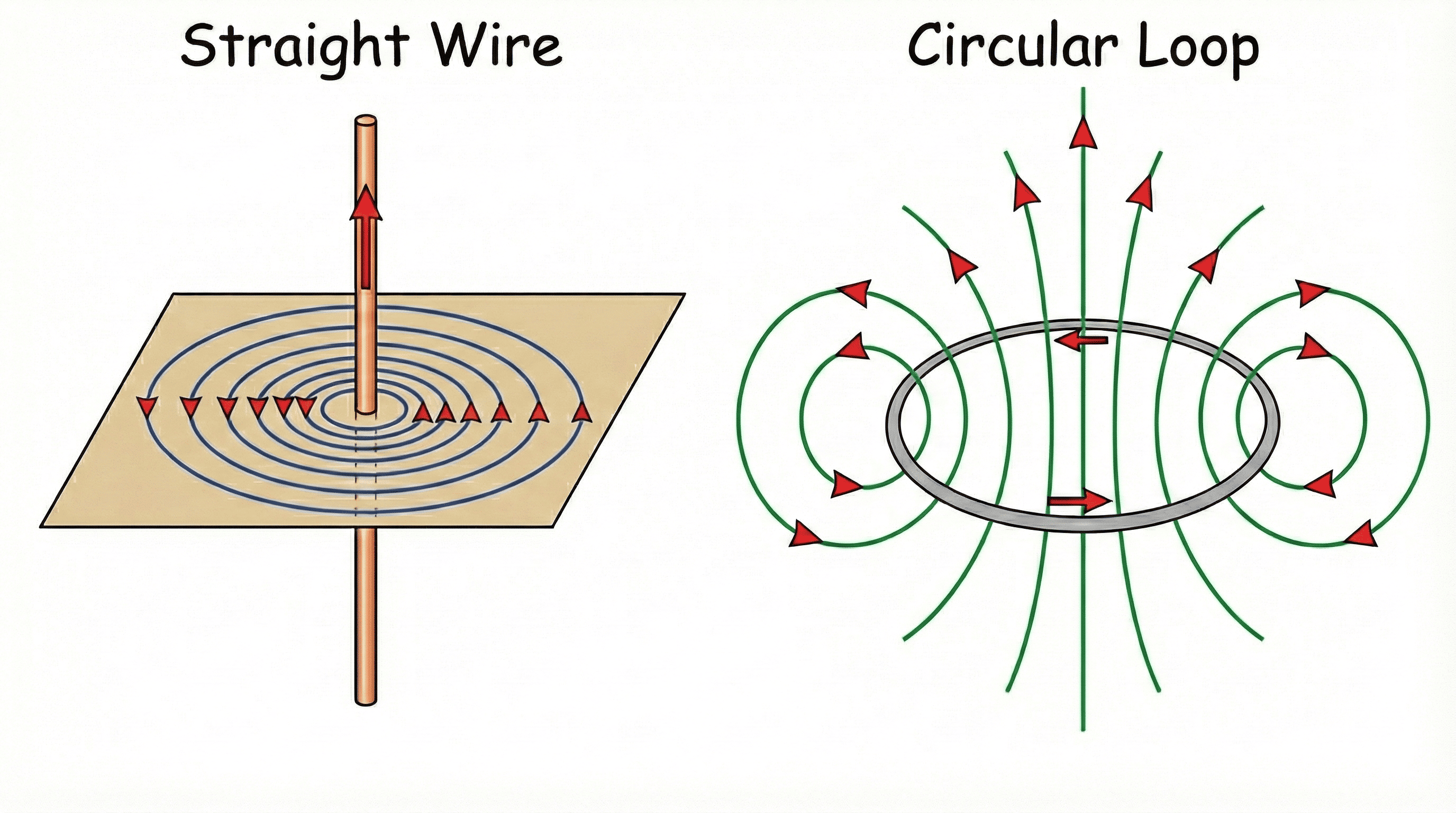 Figure 4.1: Magnetic Field due to Straight Wire & Circular Loop
2. Right-Hand Thumb Rule (Exam Definition)
What to write in Exam:
Imagine you are holding a current-carrying straight conductor in your right hand such that the thumb points towards the direction of current. Then your fingers will wrap around the conductor in the direction of the field lines of the magnetic field.
Imagine you are holding a current-carrying straight conductor in your right hand such that the thumb points towards the direction of current. Then your fingers will wrap around the conductor in the direction of the field lines of the magnetic field.
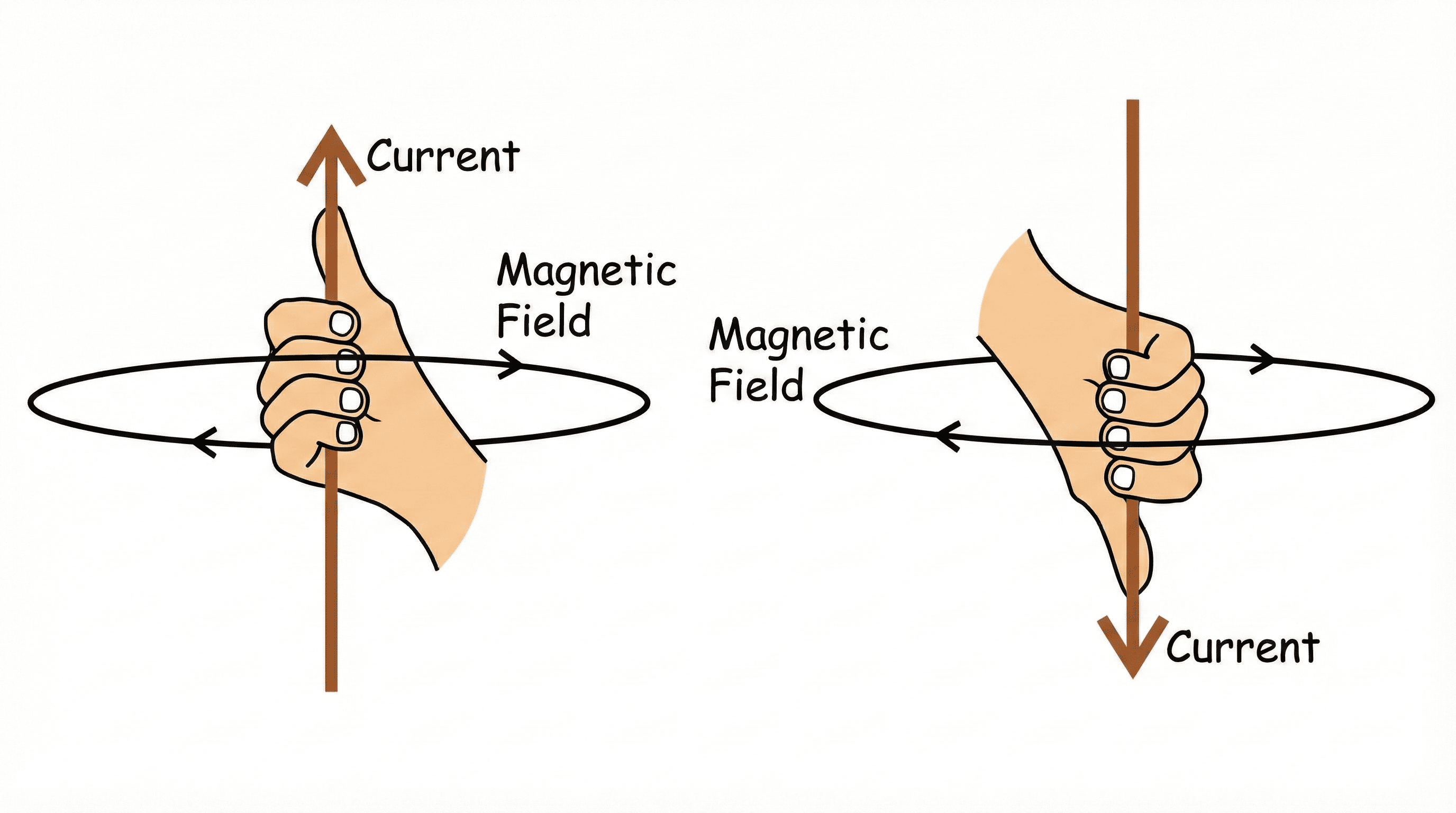 Figure 4.2: Right-Hand Thumb Rule
3. Solenoid & Bar Magnet Behavior
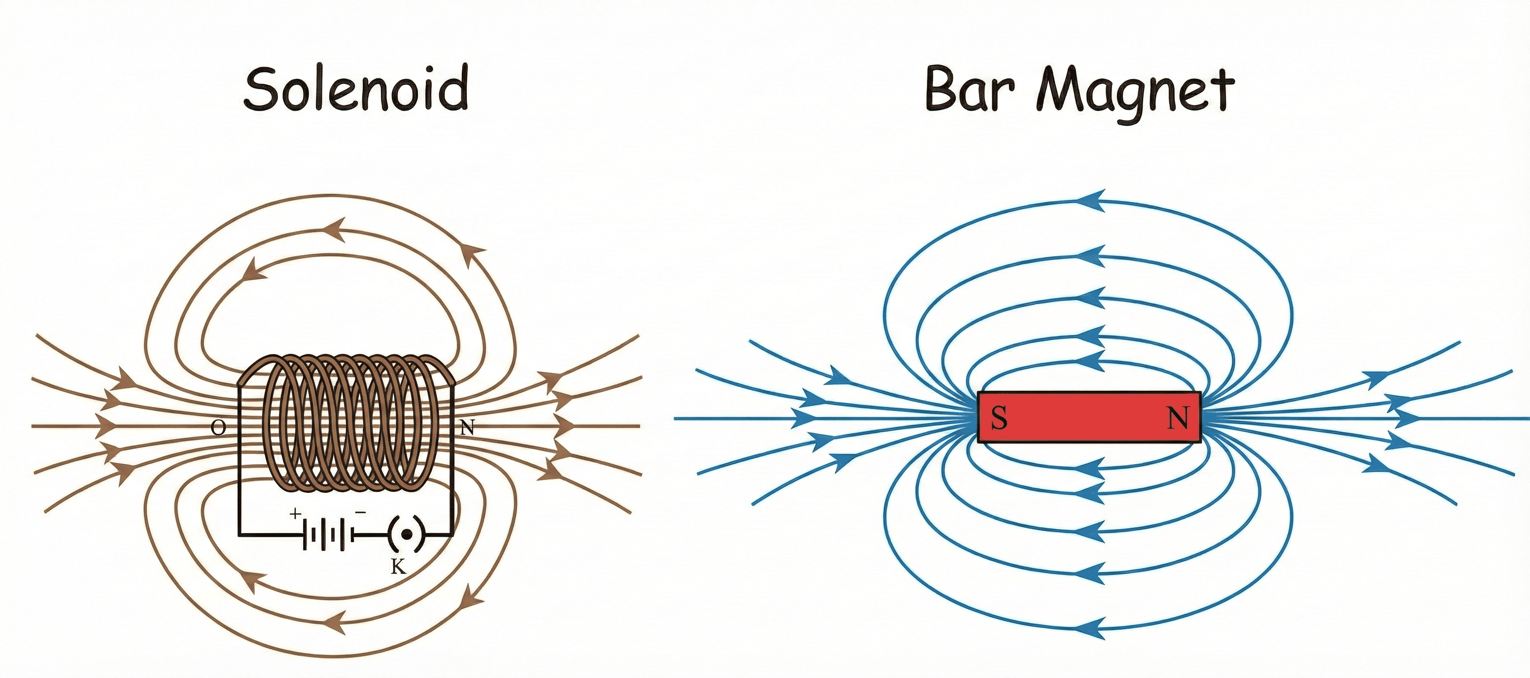 Figure 4.3: Magnetic Field Lines: Solenoid
vs Bar Magnet
Figure 4.3: Magnetic Field Lines: Solenoid
vs Bar Magnet
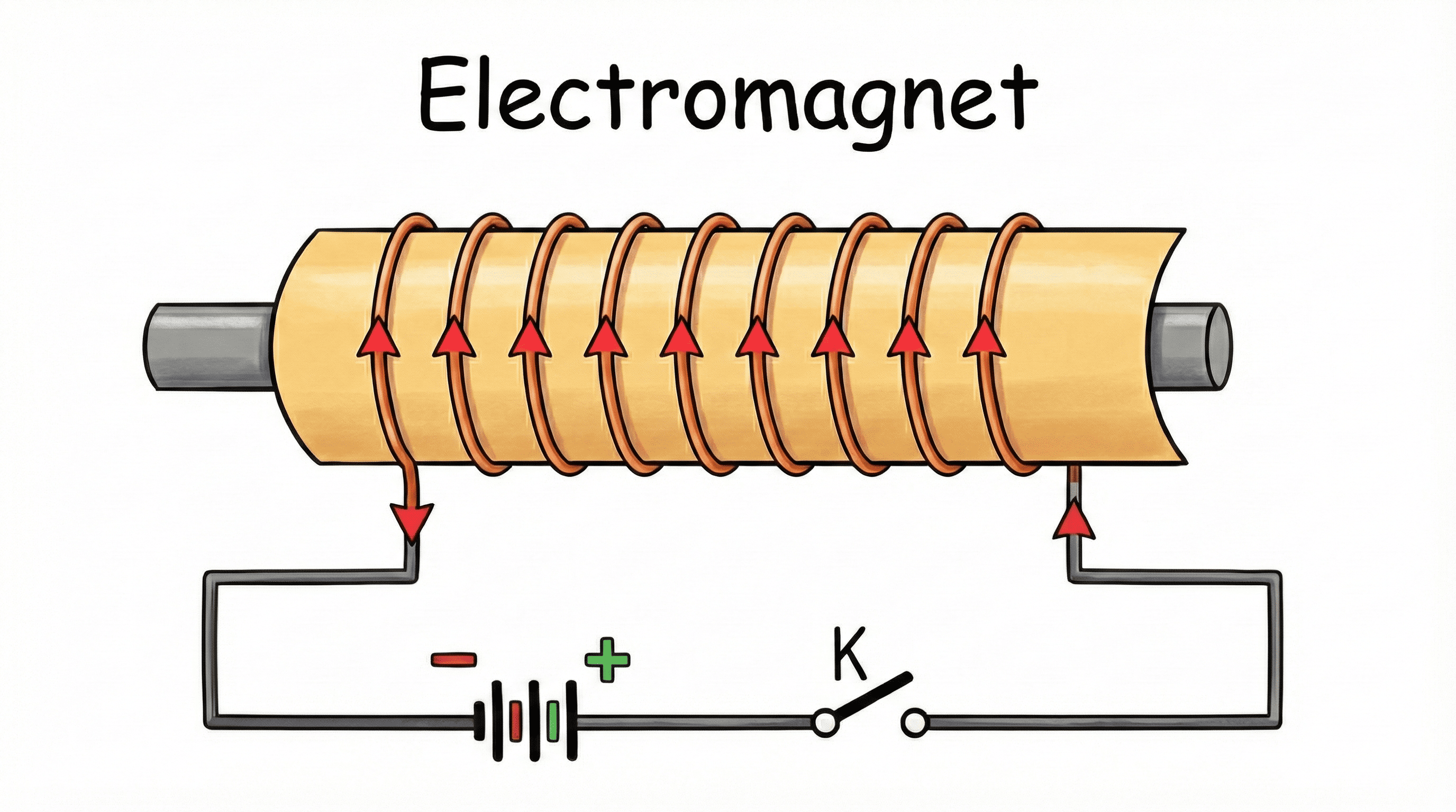
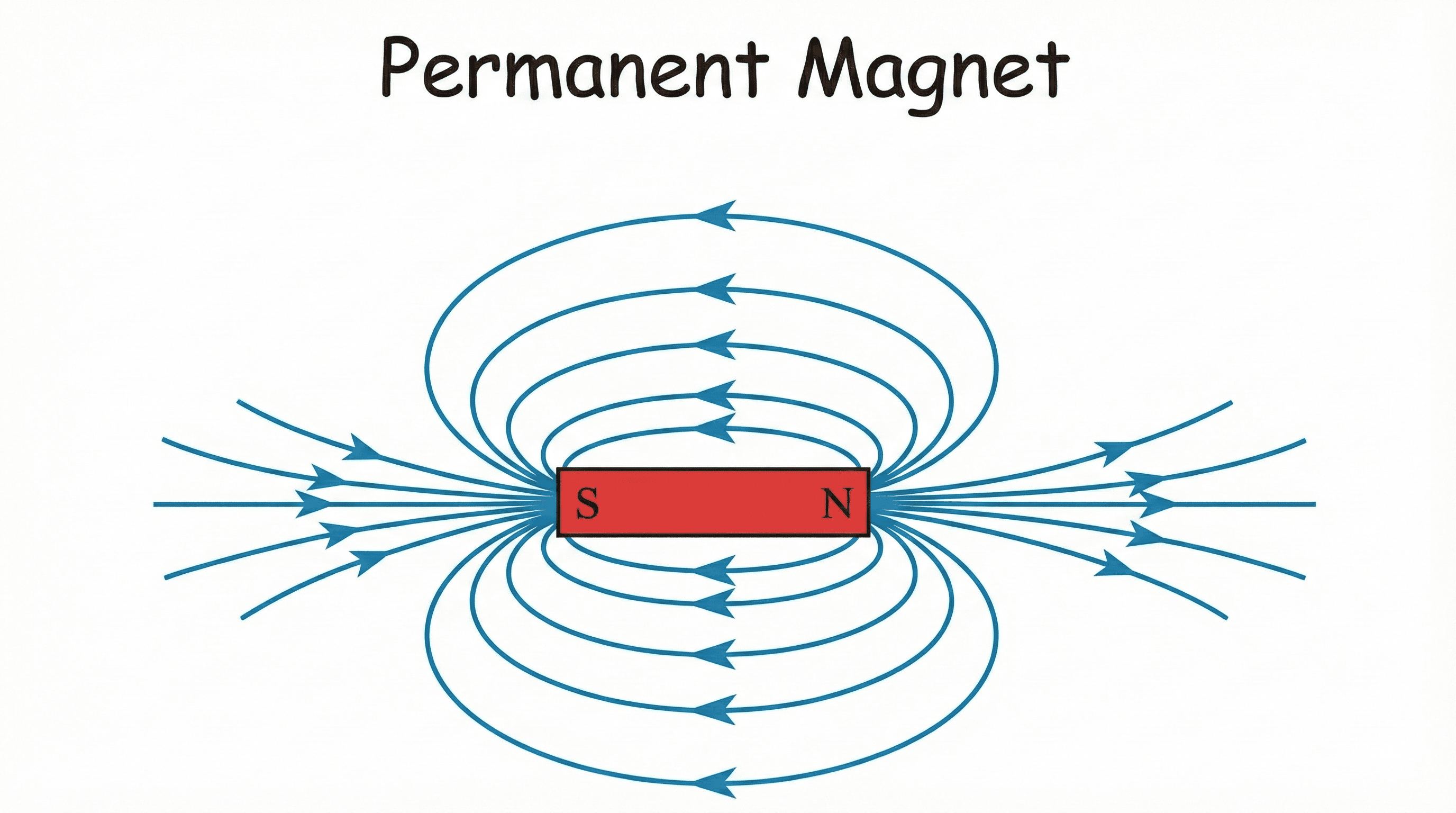
4. Electromagnet vs Permanent Magnet
|
Electromagnet (Temporary) |
Permanent Magnet |
|---|---|
|
|
| Created by current in solenoid with soft iron core. | Natural or made of steel/alloys (Alnico). |
| Strength can be changed. | Strength is fixed. |
| Polarity can be reversed. | Polarity cannot be reversed. |
5. Force on Conductor & Fleming's Left Hand Rule
A current-carrying conductor placed in a magnetic field experiences a force (Motor Principle).
Fleming's Left Hand Rule (Exam Definition):
Stretch the thumb, forefinger and middle finger of your left hand such that they are mutually perpendicular.
• Forefinger: Points in the direction of Magnetic Field.
• Middle finger: Points in the direction of Current.
• Thumb: Points in the direction of Motion (Force).
Stretch the thumb, forefinger and middle finger of your left hand such that they are mutually perpendicular.
• Forefinger: Points in the direction of Magnetic Field.
• Middle finger: Points in the direction of Current.
• Thumb: Points in the direction of Motion (Force).
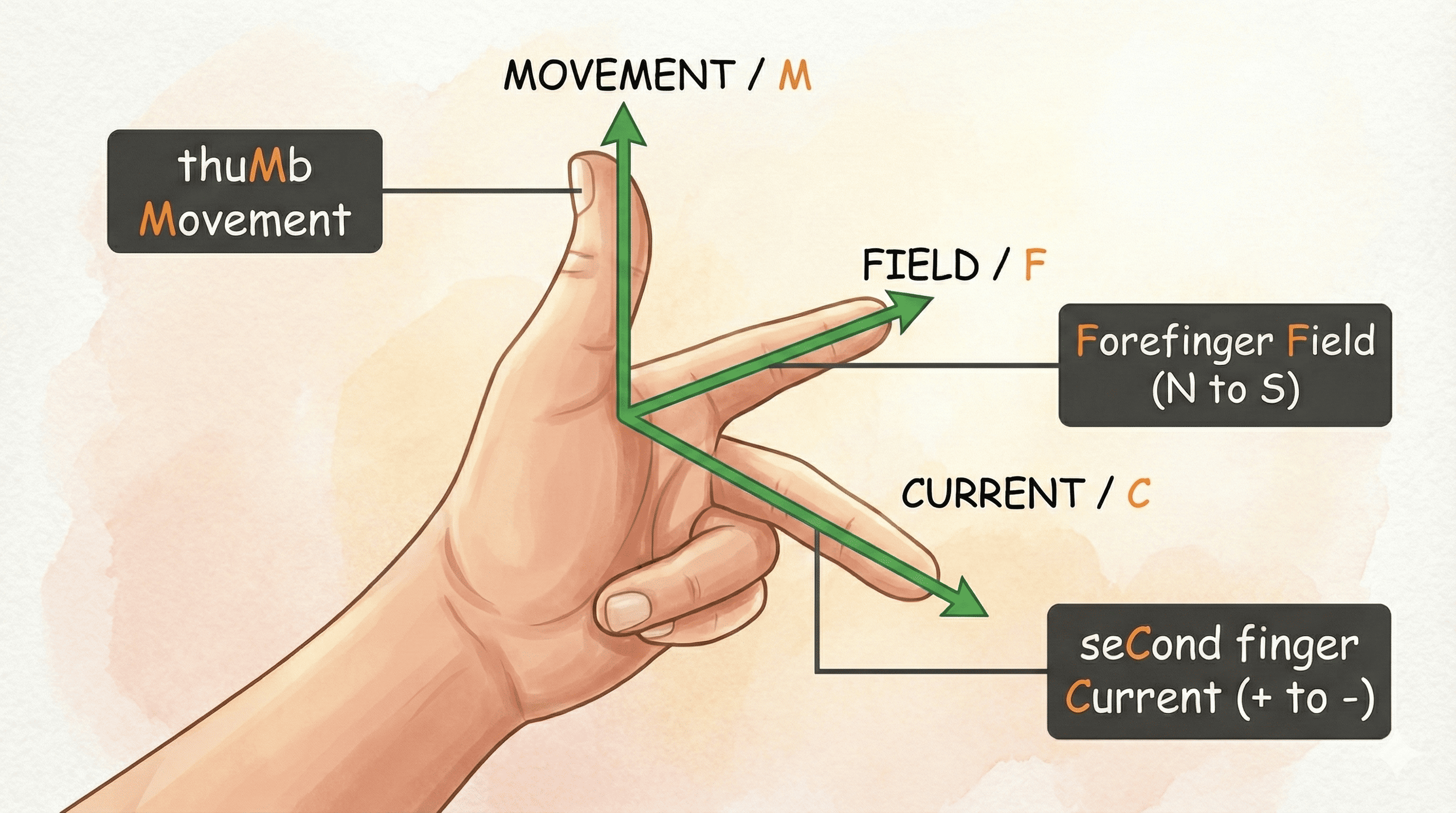 Figure 4.4: Force on Current-Carrying Conductor in Magnetic Field
6. Domestic Circuits
| Wire | New Color | Function |
|---|---|---|
| Live | Brown | Carries current (220V) |
| Neutral | Blue | Return path (0V) |
| Earth | Green/Yellow | Safety (Leakage current) |
AC vs DC (Must Know):
1. AC (Alternating Current): Direction reverses periodically (50 Hz).
2. DC (Direct Current): Unidirectional (Battery).
1. AC (Alternating Current): Direction reverses periodically (50 Hz).
2. DC (Direct Current): Unidirectional (Battery).
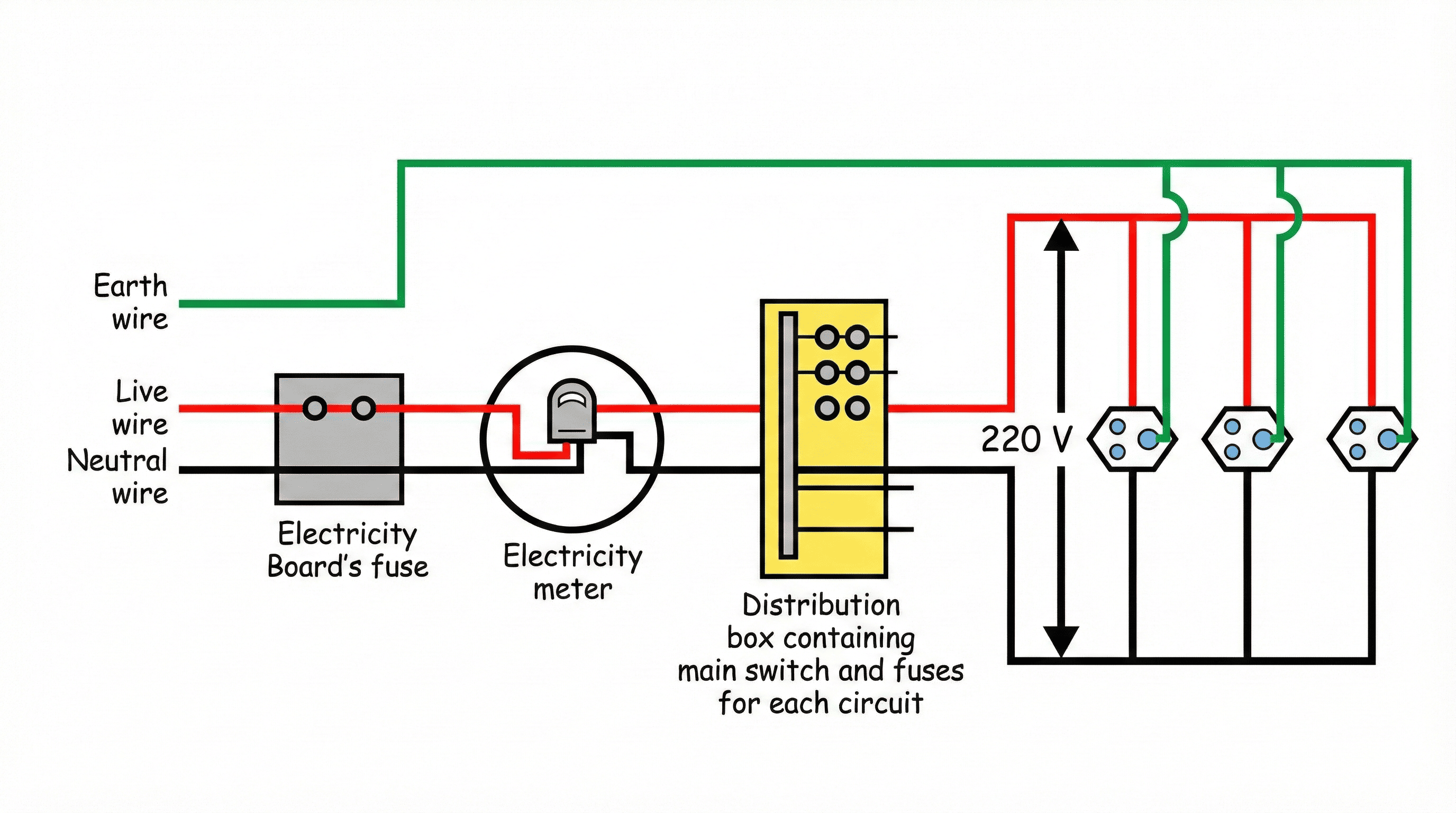 Figure 4.5: Domestic Electric Circuit